In the Fly View, missions are executed and monitored. The operator has two layouts available. By default, the map is the primary view and the video feed is the secondary view. You can change the layout by clicking the small window in the lower left corner.
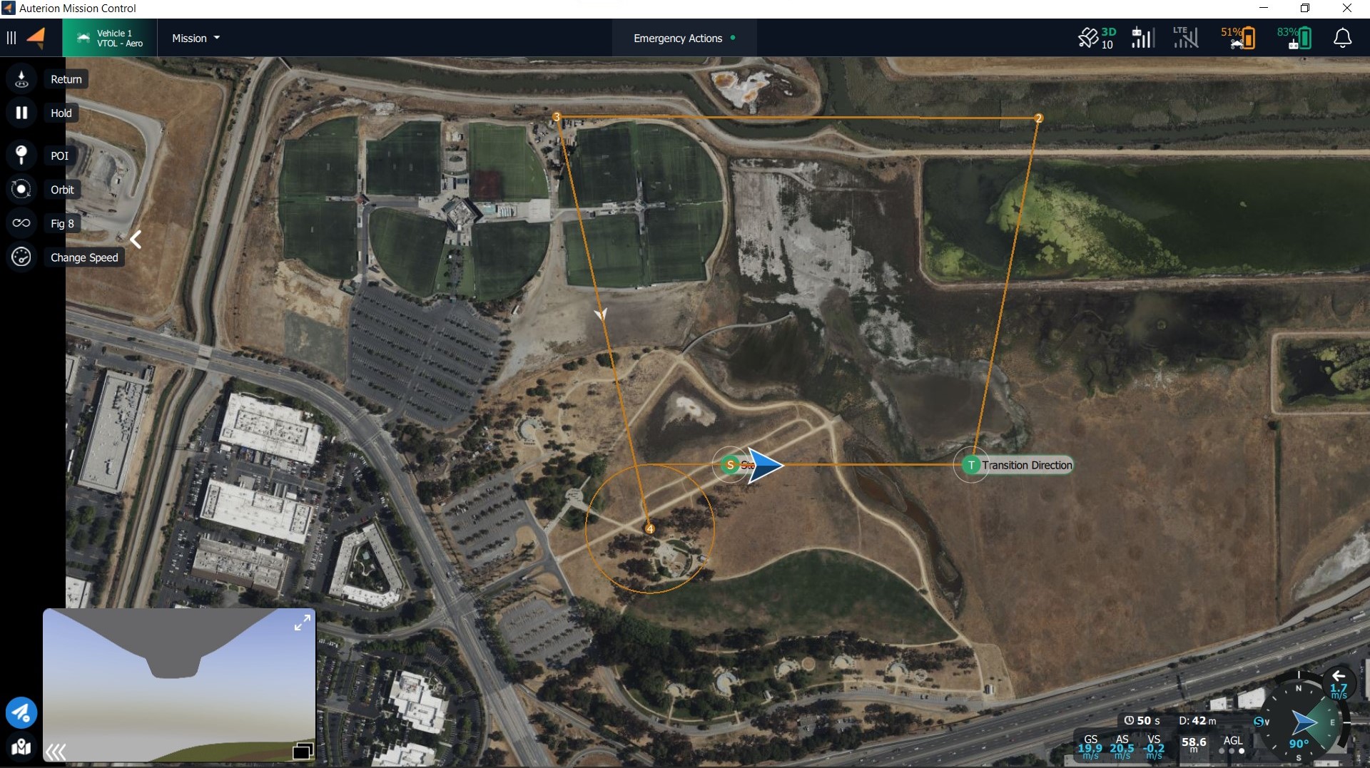
Primary view - map, secondary view - video feed:
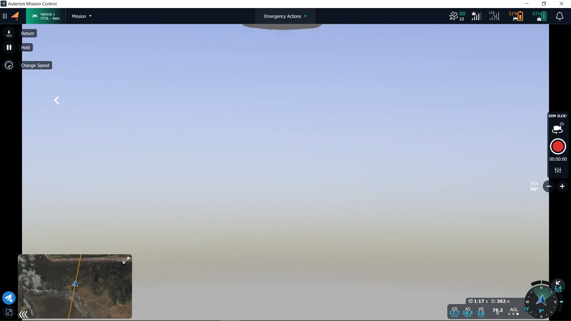
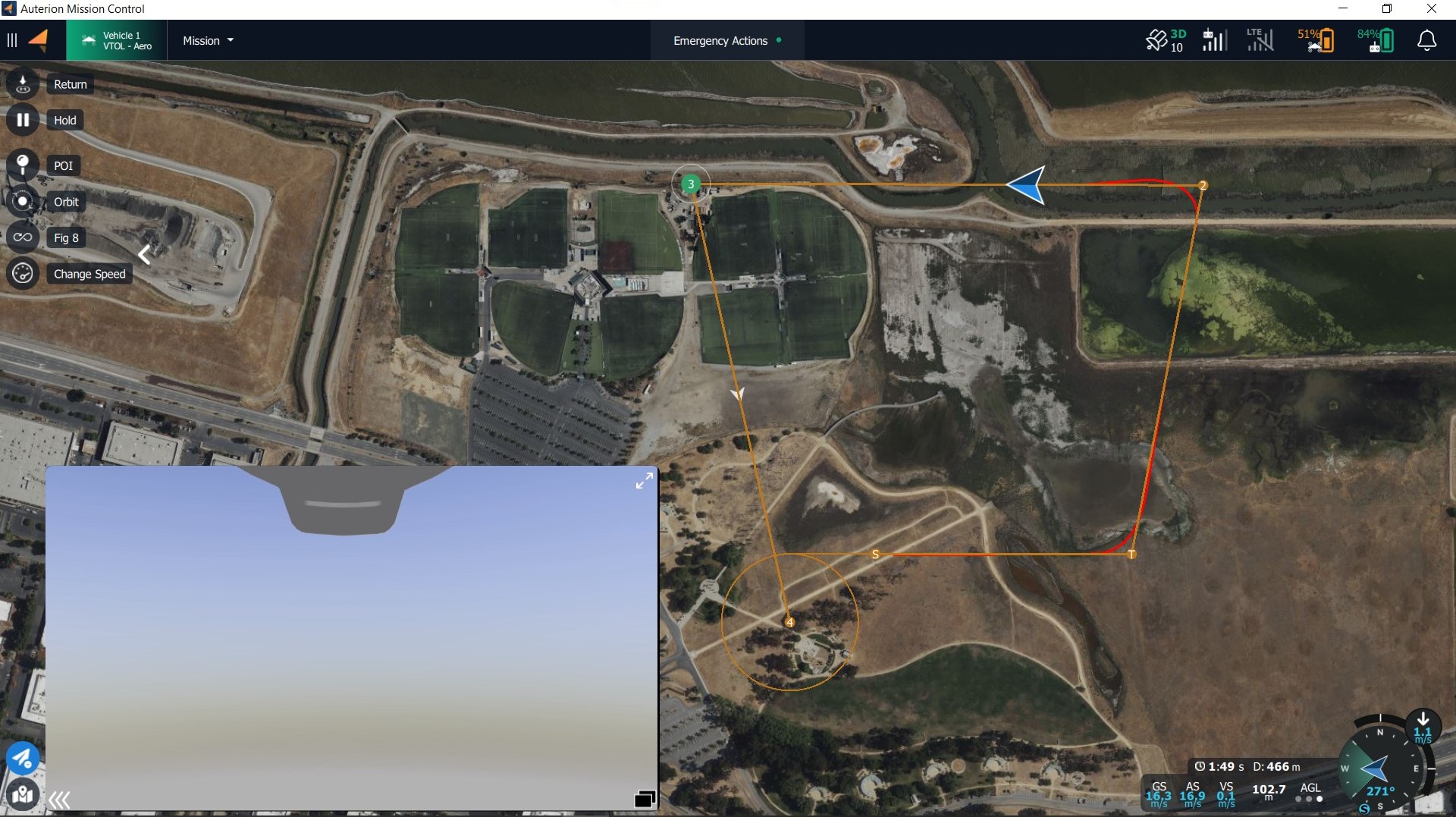
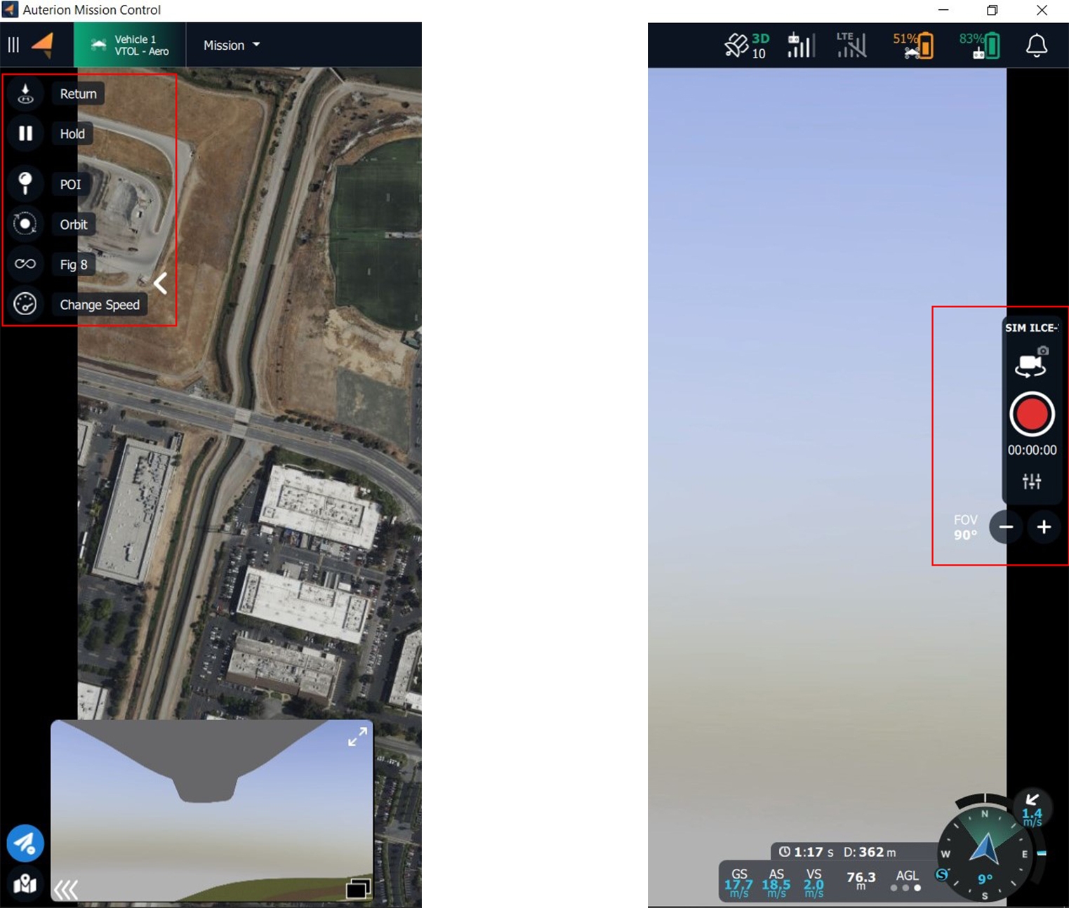
Primary view - video feed, secondary view - map view:
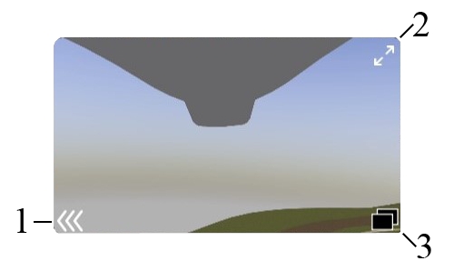
The following is a complete list of actions that can be taken within the secondary window.
Minimize or maximize the window
Adjust the size of the window
Detach the window from the lower left corner
Map is the primary view: Video is the primary view:
All Fly Tools are available Payload controls are available
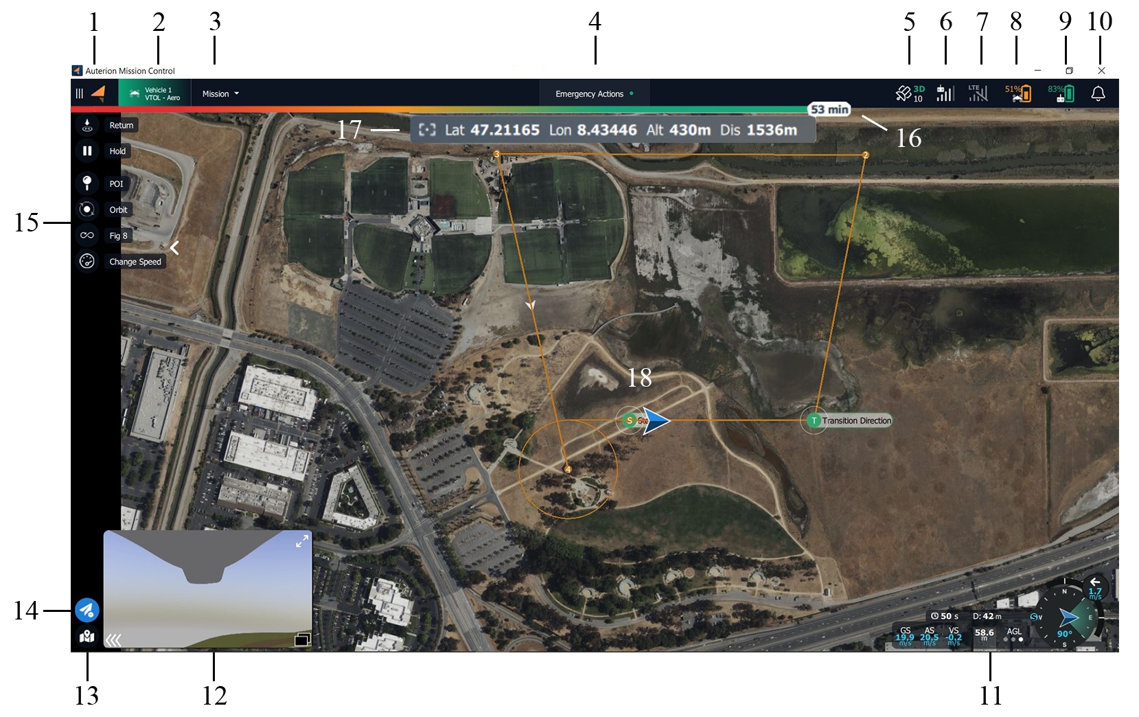
The following list describes all elements of the Fly View.
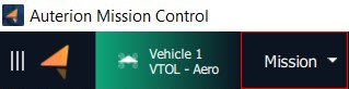
AMC Menu
Vehicle Status and Selector
Flight Mode
Emergency Actions and Arm Status
GPS Status
Radio Signal Strength
LTE Status and Signal Strength
Battery Status of the Vehicle
Battery Status of the Ground Control Station
Notifications Tab
Telemetry and Compass
Video feed
Map Tools
Flight Tools
Fly View Tools
Estimated flight Time Remaining
Additional information depending on mounted payload
Map, Mission Items, Smart Actions, Vehicle Location (blue arrow), and Vehicle Track (red trail)
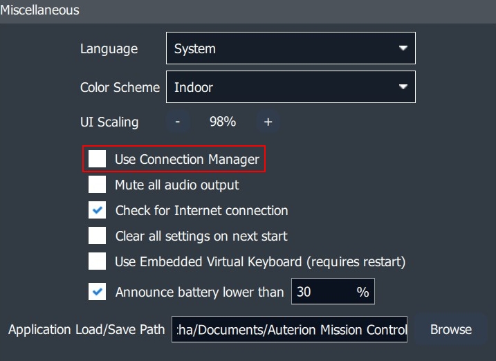
The DeltaQuad EVO does not make use of the Connection Manager. In Settings>General>Miscellanous this option can be disabled.
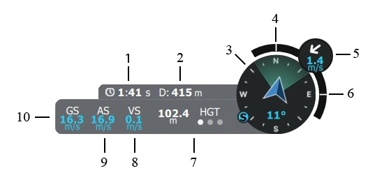
The Telemetry Panel is located in the lower right corner of the screen. It is available in both layouts when the map is the primary view and when the video is the primary view.
Time since armed (approximate flight time)
Distance between vehicle and ground station
Compass (incl. vehicle heading, camera field of view, direction towards the Ground Control Station)
Roll Index
Wind direction and wind speed
Pitch Index
Altitude display - tap the letters above the three dots to change to the different altitude measurements:
HGT
Height above takeoff
MSL
Altitude above Mean Sea Level
AGL
Altitude above Ground Level
Vertical speed
Calibrated airspeed
Ground speed/horizontal speed
The following Fly View Tools are available on the left side of the screen when the map is primary.
Takeoff
Command for takeoff - altitude, transition direction, loiter for takeoff, and approach sectors can be set.
Return
Return to the start location - the vehicle will return with the approach feature if at least one green sector is set. If no green sector is available the planned landing pattern will be ues.
Mission
Starts or resumes the planned mission.
Hold
Pauses the mission or any action. The vehicle will loiter at its current location.
Approach
Approach sector and Safe Areas can be modified.
POI
Orbit
Sets an Orbit with selectable altitude, radius, and loiter direction.
Figure of 8
Sets a figure of 8 with selectable figure size, and altitude. The figure of 8 automatically realigns when a POI is set to keep the POI in the field of view.
Change Airspeed
Enables the operator to change airspeed. When clicked the Airspeed slider appears on the right side of the screen. Values between 14m/s to 25m/s are available.
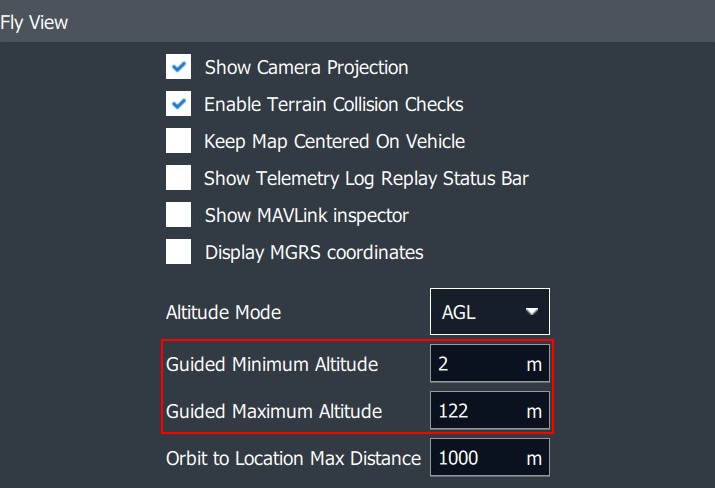
Set Altitude
The altitude of the vehicle can be changed.
These values can be changed in Settings>General>Fly View.
Center Map
Centers the map on the vehicle
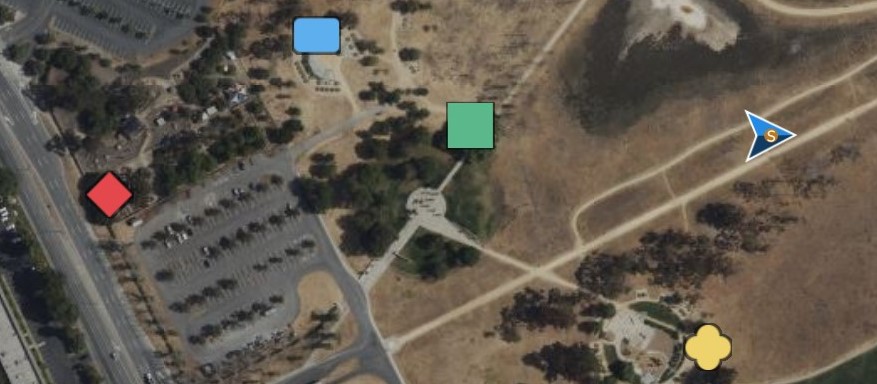
Marker
Set markers for situational awareness
Clear Path
Delete last flightpath to clear the map
Map Layers
Changes between map layers
Load KML overly
Import KML file to the map
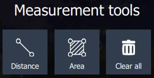
Measure
Opens the Measurement Tools
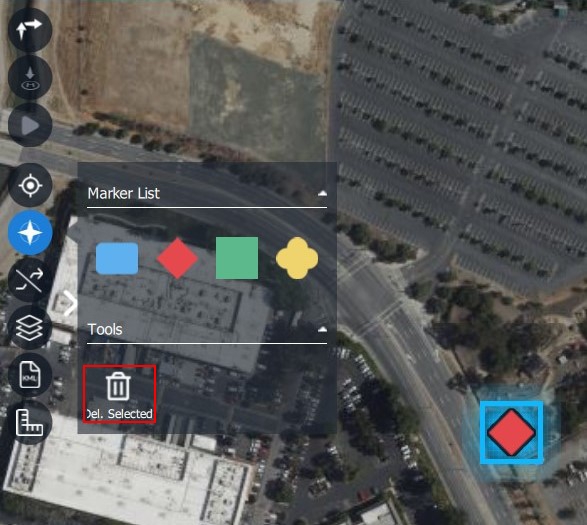
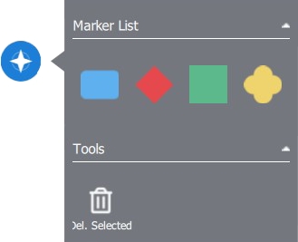
When clicking on the Marker Tool button a menu will open.
Different Marker Tool Categories can be chosen by color and form. Click on the map to set the marker.
To delete a marker, select it on the map and click on Del. Selected in the Marker Tool menu.
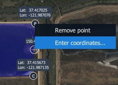
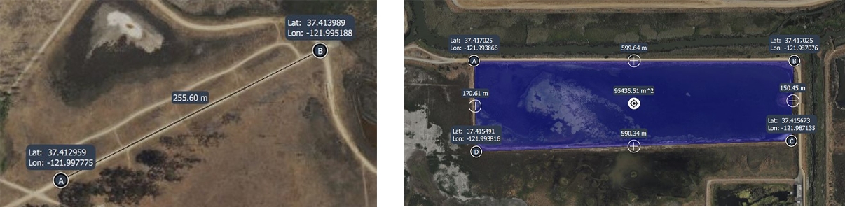
The distance between two points can be measured or the area in the form of a selectable polygon. Clear all will delete all Measurement Tools on the map.
Coordinates can be entered manually.
The third item in the upper-left corner of the screen is the Flight Mode icon.
This item displays the vehicle`s current flight mode. When clicked the operator can change to the Position flight mode for manual control.
During operation, the Flight Mode icon can display the following modes.
VTOL Takeoff
Flight mode during takeoff
Mission
Flight mode in which the vehicle executes a planned mission.
Hold
Flight mode when the Hold, Orbit, or Figure of 8 command is given.
Return
Flight mode when executing the Return command.
Land
Flight mode when Landing in the Emergency Actions has been chosen.
Position
Manual flight mode is enabled. The vehicle can be controlled with the right joystick. When there is no stick input the vehicle maintains altitude and course.
When installing Auterion Mission Control on a separate device such as a laptop or desktop pc, by default the Connection Manager will be available in the top bar of Auterion Mission Control.
Clicking the Flight Tools button in the lower-left corner of the screen will open an extra set of commands for controlling the vehicle. When the button is blue it is active and the extra set of commands will be visible. When the button is grey it is inactive and the extra commands will be hidden.
Depending on the payload a Point of Interest can be set. The camera will follow the specified location while the vehicle will remain on its flight path. The Point of Interest can be removed by clicking on Disable PIO .
When using the Set Altitude command the Altitude Slider will be presented with a fixed Minimum and Maximum Altitude. The operator can choose an altitude between these values.
Clicking the Map Tools button in the lower-left corner of the screen will open the Map Tools. When the button is blue it is active and the extra set of commands will be visible. When the button is grey it is inactive and the extra commands will be hidden.
The Marker Tool can be used to increase situational awareness. The set markers will be also displayed in the video feed.
The Measurement Tool button opens a menu.