


 will be available in the top bar of Auterion Mission Control.


| Symbol | Meaning | |
|---|---|---|
| HGT | Height above takeoff | |
| MSL | Altitude above Mean Sea Level | |
| AGL | Altitude above Ground Level |
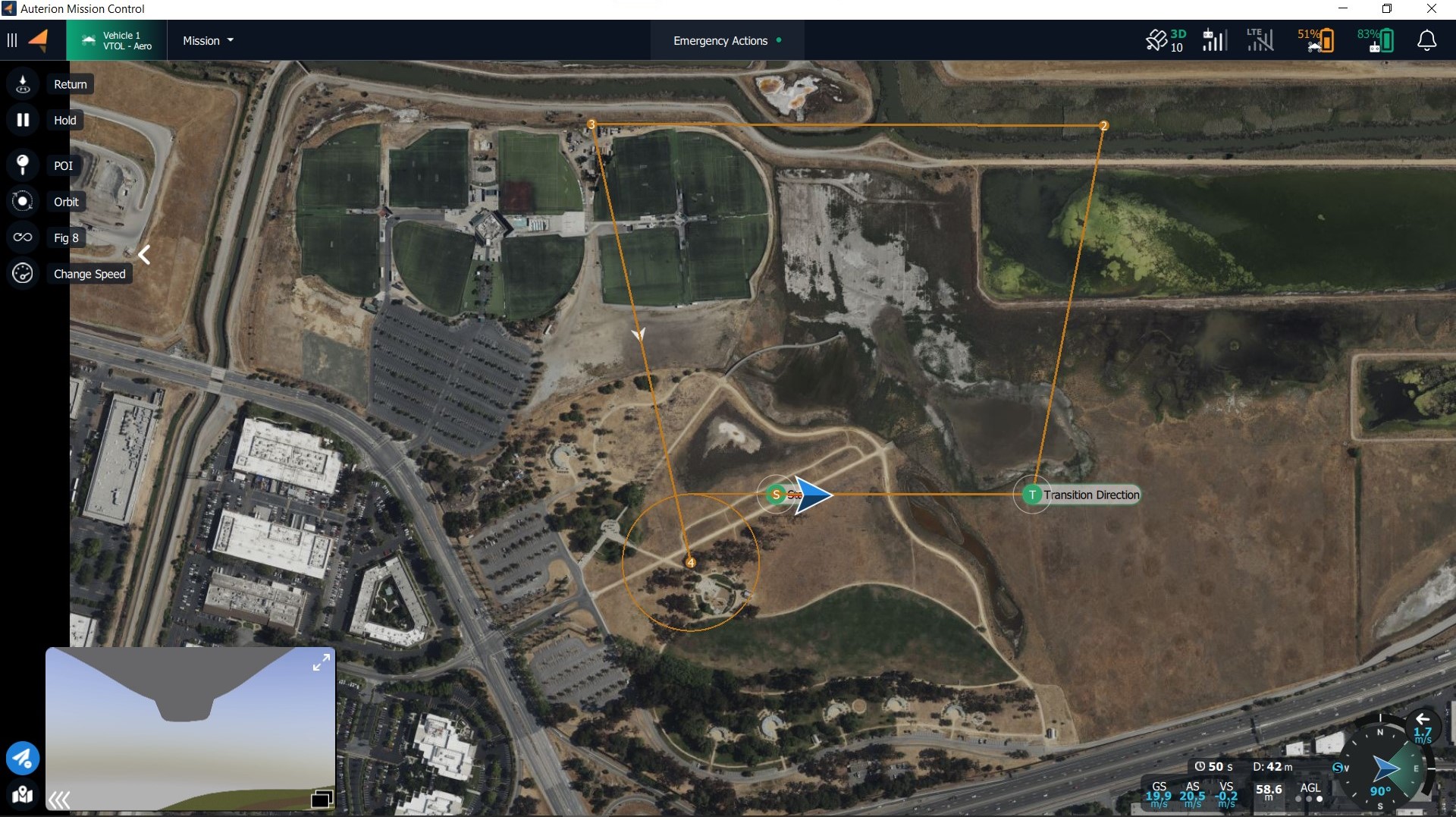
| Symbol | Command | Action |
|---|---|---|
 | Takeoff | Command for takeoff - altitude, transition direction, loiter for takeoff, and approach sectors can be set. |
 | Return | Return to the start location - the vehicle will return with the approach feature if at least one green sector is set. If no green sector is available the planned landing pattern will be ues. |
 | Mission | Starts or resumes the planned mission. |
 | Hold | Pauses the mission or any action. The vehicle will loiter at its current location. |
 | Approach | Approach sector and Safe Areas can be modified. |
 in the lower-left corner of the screen will open an extra set of commands for controlling the vehicle. When the button is blue it is active and the extra set of commands will be visible. When the button is grey it is inactive and the extra commands will be hidden.
| Symbol | Command | Action |
|---|---|---|
 | POI | Depending on the payload a Point of Interest can be set. The camera will follow the specified location while the vehicle will remain on its flight path. The Point of Interest can be removed by clicking on Disable PIO  . . |
 | Orbit | Sets an Orbit with selectable altitude, radius, and loiter direction. |
 | Figure of 8 | Sets a figure of 8 with selectable figure size, and altitude. The figure of 8 automatically realigns when a POI is set to keep the POI in the field of view. |
 | Change Airspeed | Enables the operator to change airspeed. When clicked the Airspeed slider appears on the right side of the screen. Values between 14m/s to 25m/s are available. |
 | Set Altitude | The altitude of the vehicle can be changed. |
 the Altitude Slider will be presented with a fixed Minimum and Maximum Altitude. The operator can choose an altitude between these values.
These values can be changed in Settings>General>Fly View.
the Altitude Slider will be presented with a fixed Minimum and Maximum Altitude. The operator can choose an altitude between these values.
These values can be changed in Settings>General>Fly View.

 in the lower-left corner of the screen will open the Map Tools. When the button is blue it is active and the extra set of commands will be visible. When the button is grey it is inactive and the extra commands will be hidden.
| Symbol | Command | Action |
|---|---|---|
 | Center Map | Centers the map on the vehicle |
 | Marker | Set markers for situational awareness |
| Clear Path | Delete last flightpath to clear the map | |
 | Map Layers | Changes between map layers |
 | Load KML overly | Import KML file to the map |
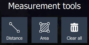
 | Measure | Opens the Measurement Tools |
 can be used to increase situational awareness. The set markers will be also displayed in the video feed.
When clicking on the Marker Tool button a menu will open.
can be used to increase situational awareness. The set markers will be also displayed in the video feed.
When clicking on the Marker Tool button a menu will open.


 opens a menu.


| Mode | Description |
|---|---|
| VTOL Takeoff | Flight mode during takeoff |
| Mission | Flight mode in which the vehicle executes a planned mission. |
| Hold | Flight mode when the Hold, Orbit, or Figure of 8 command is given. |
| Return | Flight mode when executing the Return command. |
| Land | Flight mode when Landing in the Emergency Actions has been chosen. |
| Position | Manual flight mode is enabled. The vehicle can be controlled with the right joystick. When there is no stick input the vehicle maintains altitude and course. |