This section explains how to control the Raptor 360 and Nighthawk2 camera payloads.
When bench testing the Raptor 360 or Nighthawk2 camera, it is important to provide direct cooling to the camera housing using a USB fan or a similar device.
The USB fan can be powered by a power bank or directly through the USB socket in the Evo.
Heat Generation: The Raptor 360, like many electronic devices, generates heat during operation, particularly when it is active for extended periods. Excessive heat can lead to malfunctions or permanent damage to the internal components such as the thermal sensor.
Operating Temperature: Maintaining an optimal operating temperature is crucial for the camera to function correctly. Cooling helps keep the device within its recommended temperature range.
Thermal Distortion: Overheating can cause thermal distortion, which can negatively impact image quality. This includes issues like noise in the images, reduced clarity, or incorrect color representation.
Calibration: Consistent temperatures are essential for accurate calibration of sensors. If the camera heats up, it may affect its calibration and performance during testing.
Prolonged Use: During ground testing, the camera may be operational for extended periods. Providing active cooling, such as with a USB fan, allows for longer testing sessions without risking overheating.
Performance Evaluation: To accurately evaluate the camera's performance, it should be tested under conditions that reflect its actual usage scenarios. Keeping it cool helps simulate realistic operational conditions.
Avoiding Failures: Consistent cooling can help reduce the risk of system failures during critical operations. An overheated device can shut down unexpectedly, leading to loss of data or interruption of important tasks.
Component Lifespan: By keeping the Raptor 360 cool, you can potentially extend its lifespan, reducing the need for repairs or replacements.
When the DeltaQuad Evo and the GCS are powered and connected, the video feed will be visible in AMC on the small video screen in the Fly View's bottom-left section.
You can toggle between the video being the primary view or the map being the primary view by clicking on the small screen in the lower-left corner.
For more information please review the chapter about the Fly View.
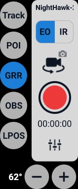
When the video feed is the primary view, the camera controls appear on the right side of the screen.
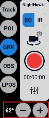
The camera controls allow you to set the following camera modes:
Track
By pressing the Track button and subsequently choosing an object within the video display, you can instruct the gimbal to track that specific object. This functionality is most effective when there is a clear contrast between the object and its background.
Target tracking is the mode where the camera will remain focused on a target. The target can be moving or static. Activate target tracking by tapping on the Track button. Simply tap anywhere in the video feed and the camera will enter tracking mode and track the target that was tapped on. You can tap several times to fine-tune your target tracking mode.
When a target is being tracked, a white square is displayed on the object that is being tracked. By moving the camera joystick, tracking is disabled and the camera returns to the previous mode.
POI
You can establish a Point of Interest (POI) on the map view by simply tapping the POI button and then tapping on your desired location on the map. Alternatively, you can set a POI while in camera view by selecting the POI option and tapping on the specific point of interest within the video frame. The gimbal will then make an effort to maintain focus on the selected POI's location on the ground.
GRR
In this mode, the camera will hold its position relative to the ground. This is the recommended mode for camera control. The joystick controls the camera.
OBS
In this mode, the camera will hold its position relative to the vehicle's movement. The joystick controls the camera.
LPOS
LPOS (Local Position) is the mode in which the camera tracks the orientation of the aircraft, so when it makes a turn, the camera maintains the same angle relative to the aircraft.
EO (Electro-optical)
Activates the RGB (normal color video) mode of the camera.
IR (Infra-red)
Activates the Infrared camera for night vision and seeing between foliage.
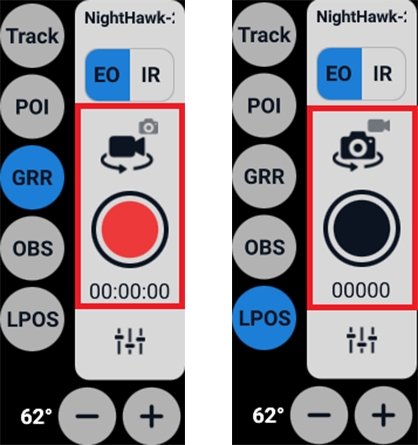
When clicking on the camera symbol the recording mode can be switched between photo and video recording.
The red button indicates the video recording mode.
The black button indicates the photo recording mode.
The -/+ button controls the zoom of the camera. The zoom level is indicated by degrees.
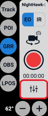
The fader button opens the camera menu with access to camera settings and general settings.
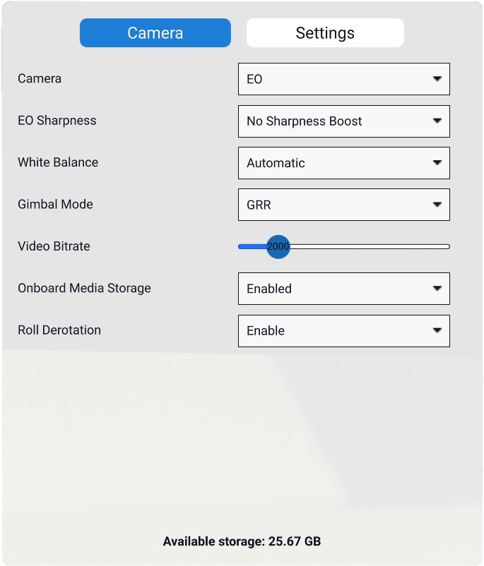
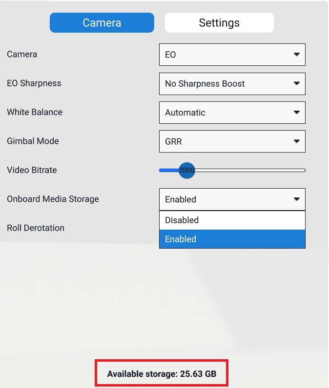
The camera settings tab gives access to the following options:
Camera: Switch between EO and IR mode. This mode can be also accessed via the camera controls in the Fly View.
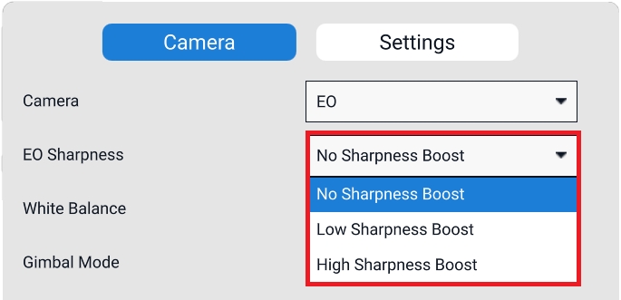
EO Sharpness: This option gives three different degrees to boost the sharpness of the image.
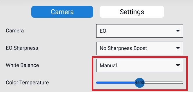
White Balance: Switch between Automatic and Manual mode.
When White Balance is set to Manual a slider appears to set the white balance manually:
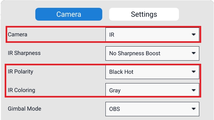
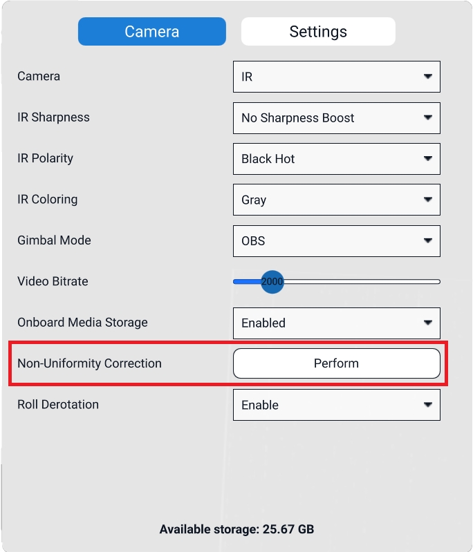
When IR is chosen as the camera mode more options will be available for this mode:
IR Polarity: In this tab, the operator can choose to have either Black Hot or White Hot.
IR Coloring: In this tab, the operator can choose between the Gray scale or the Color scale.
Non-Uniformity Correction (NUC): After engaging the IR mode, the IR camera needs to be calibrated for a clear view. This is done automatically by the system. NUC performs this calibration which takes about 3 seconds.
It is recommended to use a uniform field for calibration and to avoid variable heat sources in the field of view during NUC.
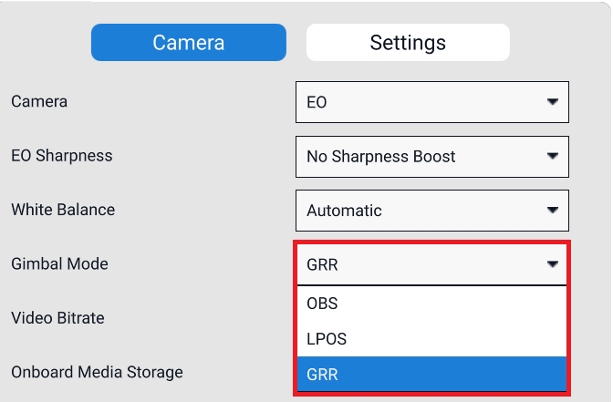
Gimbal Mode: In this tab, the operator can switch between GRR, OBS, and LPOS gimbal modes. These camera control options are also available in the Fly view via the camera controls.
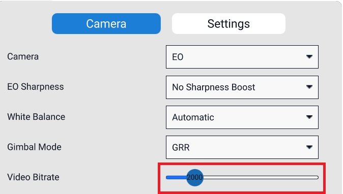
Video Bitrate: With this slider the video bitrate can be set. By default, the value is set to 2000. The higher the bitrate the better the video image will be but at the cost of the maximum telemetry distance.
Onboard Media Storage: With this option, you can enable or disable the Onboard Media Storage. When enabled, the media will be stored on the SD card in the Trip board computer located in the payload. When disabled, the media will be stored on the GCS.
At the bottom of the window, the available storage for video recording will be displayed.
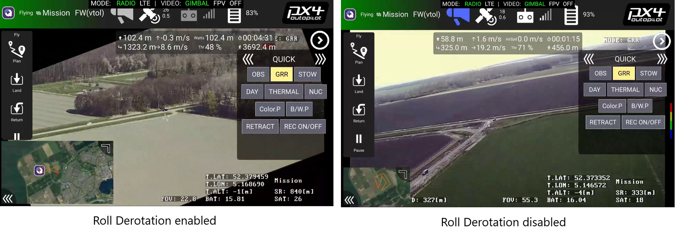
Roll Derotation: The camera is capable of keeping the video stream aligned with the horizon when the vehicle is banking. This is called roll derotation.
When roll derotation is active the video image displayed on the controller will rotate in such a way that the image remains level. The trade-off is that the video can show black corners when the vehicle is banking.
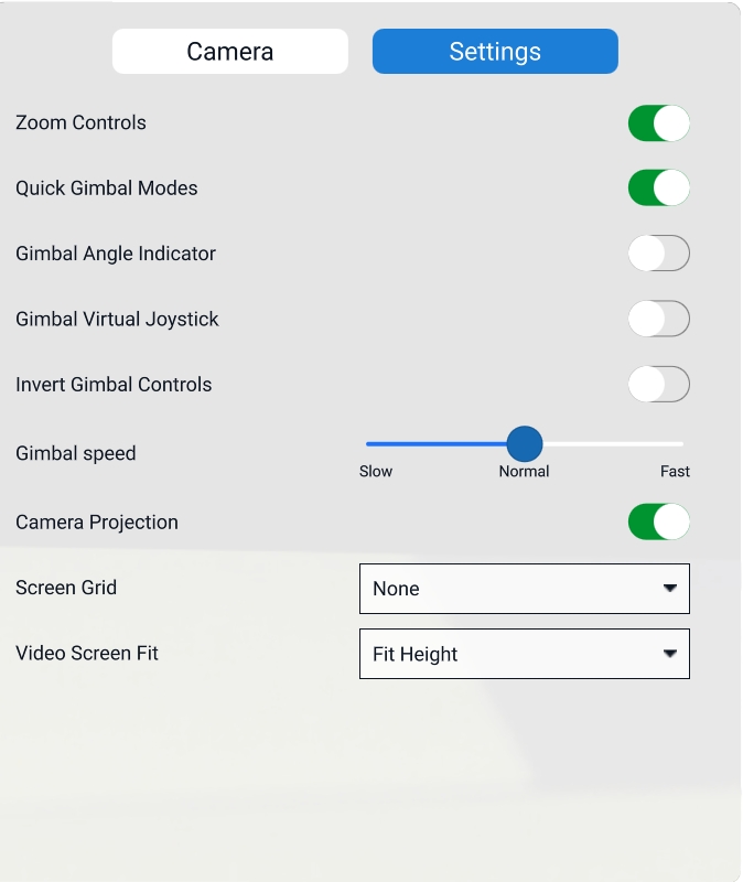
The Settings tab on the upper right corner of the menu gives access to general settings:
Zoom Controls
Enables zoom controls in the camera control window.
Quick Gimbal Modes
Makes the gimbal modes (GRR, OBS, and LPOS) available in the camera control window.
Gimbal Angle Indicator
The camera angle (in degrees) will be displayed in the Fly view.
Gimbal Virtual Joystick
Enables a virtual joystick left of the camera control interface in the Fly view.
Invert Gimbal Controls
Inverts the gimbal controls.
Gimbal speed
With the slider, the gimbal speed can be set. It is set to Normal by default.
Camera Projection
Screen Grid
This option will display a grid overlay on top of the video image.
The grid option is either a square or a screen division by 3x3:
Target following is the mode where the vehicle actively follows a tracked target. To engage target following mode you will first need to track a target. Once a target is locked you can engage target following by giving the Target Following command. The command is located on the left side of the Fly View where the pilot commands are located.
The system will start following a target when these conditions are met:
A target is actively being tracked
The target is less than 2,000 meters away from the vehicle
Target following has been enabled
When entering target following the vehicle will issue reposition commands for as long as the target following conditions are met. If the conditions are no longer met the vehicle will remain circling the position of the last known target location. If the tracked target is lost you can re-engage target tracking by simply tapping on the object in the video feed, the system will follow any target selected while target following is enabled and the conditions are met.
If the vehicle is flying above the tracked target, or if the vehicle is flying faster than the tracked target, it will circle above the target keeping the target in view at all times.
If target following is disengaged the vehicle will start circling its current position.
When the map is the primary view, a Point of Interest (POI) can be established by clicking on the POI button on the left side of the screen.
The POI button will be available when the Flight Tools are selected (the paper plane in the lower-left corner).
Tap the desired location on the map, and the gimbal will attempt to maintain focus on the selected POI's location on the ground.
To cancel a POI click the button Cancel POI in the upper left corner of the screen.
Alternatively, you can set a POI while in camera view (video feed is primary view) by selecting the POI option in the camera controls and tapping on the specific point of interest within the video frame.
When a POI is selected in the video feed, it will also be visible on the map at the center of the camera projection.
Whenever a POI is selected or an object is tracked, its geolocation and slant range are displayed at the top of the screen, directly under AMC's Top Bar.
Slant Range (SR) is the straight-line distance from a sensor to a target, measured along the line of sight, accounting for elevation differences.
Slant range calculations are more accurate when the camera is angled downward rather than horizontally. A downward angle maximizes the vertical component of the distance to the target, reducing distortion and obstructions, and provides a clearer line of sight. This is especially important when the tracked object is at a different elevation than the ground underneath the vehicle. In contrast, a horizontal view increases the horizontal distance and minimizes the vertical component, leading to less reliable slant range measurements.
Vertical Component Maximization: When the Raptor camera is angled downward, the vertical component of the distance to the target is greater relative to the horizontal distance. This makes it easier to calculate the slant range accurately, as the sensor can more effectively measure the distance to the target without the influence of excessive horizontal distance.
Perspective and Distortion: A downward angle reduces perspective distortion because the camera views the target more directly. In contrast, a horizontal view can exaggerate distances due to the angles involved, making it harder to ascertain precise distances.
Elevation Differences: When the tracked object is at a different elevation, a downward angle helps capture that elevation difference more effectively. If the camera is horizontal, the accuracy of slant range calculations can be compromised, especially if the object is significantly higher or lower than the UAV's altitude.
Obstructions: A downward angle helps avoid obstructions in the foreground that could interfere with the line of sight to the target. Horizontal views may have more potential obstructions affecting the clarity and accuracy of the tracking.
If no POI is selected and no object is tracked, the Geo-Tracking Dashboard will display the values corresponding to the camera's center field of view.
When the map is selected in the Fly View the camera's Field of View is indicated by a cone.


