Loading...
Loading...
Loading...
Loading...
Loading...
Loading...
Loading...
Loading...
Loading...
Loading...
This section explores the various elements of the Fly View.
In the Fly View, missions are executed and monitored. The operator has two layouts available: by default, the Map is the Primary View, while the Video Feed is the Secondary View. You can change the layout by clicking the small window in the lower-left corner.
Primary View - map, Secondary View - video feed:
Primary view - video feed, Secondary View - map:
The smaller Secondary Window in the lower-left corner can be resized by clicking the two arrows in the upper-right corner. Drag the window to adjust it to your desired size.
The following list outlines the actions that can be performed within the Secondary Window.
Minimize or maximize the window.
Adjust the size of the window.
Detach the window from the lower-left corner.
The available Fly Tools change depending on whether the map or video feed is the Primary View. When the map is the Primary View, all Fly Tools are accessible. Conversely, when the video feed is the Primary View, the payload controls on the right side of the screen become available.
Map is the Primary View: All Fly Tools, Flight, and Map Tools are available (when running AMC in Advanced Mode) on the left side of the screen.
Video Feed is the Primary View: Payload controls, if applicable (in this example, ISR payload), are available on the right side of the screen, while Fly Tools (selection), Flight, and Map Tools are accessible on the left side.
The available payload controls depend on the mounted payload. The different payload controls will be discussed separately in their dedicated sections.
The following list outlines all the elements of the Fly View.
For a detailed overview of AMC's Top Bar items, please revisit the chapter AMC Top Bar.
AMC Menu
Vehicle Status Indicator
Flight Mode Selector and Indicator
Emergency Actions and Arm/Disarm Status
Radio Link Indicator/Selector
GPS Status/GPS Fusion
Data Link Signal Strength Indicator
LTE Status and Signal Strength Indicator
Vehicle Battery Status/Energy Consumption
GCS Battery Status
Telemetry Dashboard
Video Feed (payload-dependent)
Map Tools
Flight Tools
Fly Tools (Quick Access)
Estimated Flight Time Remaining
Geo-Tracking Dashboard (ISR payload)
Map, Mission Items, Smart Actions, Vehicle Location (blue arrow), and Vehicle Track (red trail)
When zooming in and out, a Scale Indicator appears at the bottom of the screen to show the current zoom scale. To use the zoom function, you can either use the mouse wheel or the touchscreen. It indicates the scale of the map based on the zoom level.
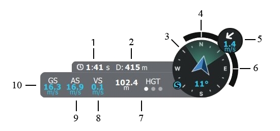
The Telemetry Dashboard is located in the lower-right corner of the screen. It is available in both layouts, whether the Map or the Video is the Primary View.
Time Since Armed (approximate flight time)
Distance Between Vehicle and Ground Station
Compass (includes vehicle heading, camera field of view, and direction towards the Ground Control Station)
Roll Index
Wind Direction and Wind Speed
Pitch Index
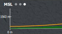
Altitude Display - Tap the letters above the three dots to switch between different altitude measurements
HGT
Height (Heights are referenced to the takeoff location)
MSL
Mean Sea Level (Altitude Above Mean Sea Leve)
AGL
Above Ground Level (Altitude Above Ground Level)
Vertical Speed
Calibrated Airspeed
Ground Speed/Horizontal Speed
Basic flight operations are initiated by pressing the appropriate button in the Fly Tools. Fly Tools are useful even during manual flight, as they streamline tasks such as Takeoff and RTL. Only the valid tool options for the current vehicle state are displayed, while invalid options are either hidden or grayed out.
Clicking the arrow opens the sidebar, revealing the title next to each icon.
The following Fly Tools are available on the left side of the screen when the Map is in Primary View.
Takeoff
Commands for (Quick) Takeoff—Altitude, Transition Direction, Loiter for Takeoff, and Approach Sectors—can be set.
Return
Return to Launch – The vehicle will return using the approach feature if at least one green sector is set. If no green sector is available, the planned landing pattern will be used.
Hold
Pauses the mission or any ongoing action. The vehicle will loiter at its current location.
Mission
Starts or resumes the planned mission.
All of the above actions will require user confirmation before execution.
The following Flight Tools are available on the left side of the screen when the Map is in Primary View and AMC is running in Advanced Mode.
POI
Orbit
Sets an Orbit with selectable altitude, radius, and loiter direction.
Figure of 8
Sets a Figure-8 with selectable size and altitude. The Figure-8 automatically realigns to keep the POI in view when a POI is set.
Change Airspeed
Enables the operator to change the Airspeed. When clicked, the Airspeed Slider appears on the right side of the screen, with values ranging from 14 m/s to 23 m/s available.
Land
Multirotor Mode (Hover): Land the vehicle at the current location and disarm (option visible if flying).
Fixed-wing Mode (Aero): Transition to Multirotor Mode (Hover) and land at the current location.
VTOL Transition
VTOL Transition is used to toggle a transition between VTOL Fixed-wing (Aero) and Multirotor (Hover) modes. (Only available in AMC Advanced Mode).
Target
Following
The vehicle actively follows a tracked target. To engage in Target-Following mode, you must first track a target.
All of the above actions will require user confirmation before execution.
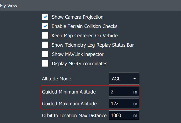
When using the Orbit or Figure-8 command, the Altitude Slider is presented on the right side of the screen with a fixed minimum and maximum altitude. The operator can choose an altitude between these values.
These values can be changed in AMC menu -> Settings -> General -> Fly View.
The following Map Tools are available on the left side of the screen when the map is in Primary View and AMC is running in Advanced Mode.
Center Map
Centers the map on the vehicle or GCS location, if available.
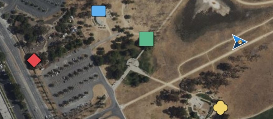
Marker
Place markers to enhance situational awareness.
Clear Path
Delete the flight path to clear the map.
Map Layers
Switch between map layers.
Load KML overly
Import a KML file to the map.
Measure
Opens the Measurement Tools.
Different Marker Tool categories can be selected by color and shape. Click on the map to set the marker.
On the right side of the screen, an option will be available to set coordinates for the specific marker.
To delete a marker, select it on the map and click on the small Trash Bin.
To delete all markers, click on the Trash Bin icon in the Marker Tool menu.
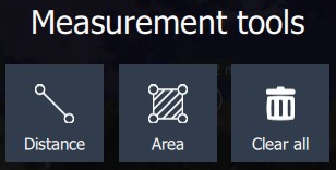
The distance between two points can be measured, or the area can be calculated as a selectable polygon. Selecting Clear All will delete all Measurement Tools on the map.
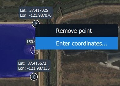
Coordinates can be entered manually, and specific points can be removed.
The Fly View presents important warnings in a highly visible popup, alerting you to any unexpected behavior or issues. When possible, the notification will also provide the cause of the problem and suggest any required actions. Less critical messages, along with any missed warnings, are logged and can be accessed in the Vehicle Overview.
This section provides an overview of all available options and settings in the AMC menu.
Auterion Mission Control offers two main views. In the Fly View, you execute and monitor missions.
The Plan View is used to plan autonomous missions for your vehicle. Once the mission is planned and uploaded to the DeltaQuad Evo, you switch to the Fly View to perform the Pre-flight Checks and execute the mission.
The AMC Menu gives access to the following sub-menus and settings.
For ease of use, all presented sub-menus and settings are those accessible when operating AMC in Advanced Mode and when the vehicle is powered on and connected to the GCS. If you cannot find a menu, switch to Advanced Mode and connect the vehicle to the GCS.
Fly
Fly View is used for all operations related to monitoring and controlling vehicle flight. It is the default view displayed on application start.
Plan
Plan View is used to plan autonomous missions, which may include Survey Scans, Corridor Scans, and Geofences.
Vehicle Overview
The Vehicle Overview offers operators an easy way to access the Sensors, Connectivity, and Active Tasks tabs. At the bottom of the window, the automated Preflight Checklist, Safety, and Cloud features are accessible. Under the More tab, GPS Advanced Settings are available if applicable (Tactical and Stealth Editions only).
Advanced
Provides a summary of the vehicle settings and access to sub-menus such as Storage and Parameters. These settings and menus are not relevant for typical drone operators and should not be changed by end users, except when instructed.
Controller
This menu provides the option to test and set up a traditional remote controller or a USB joystick, such as the DeltaQuad Evo handheld controller.
Photos
View photos and videos downloaded from the vehicle. The file location on the GCS can be accessed with a single click.
Analyze
Gives access to Log Download, GeoTag Images, MAVLink Console, and MAVLink Inspector. These settings and menus are not relevant for typical drone operators and should not be changed by end users, except when instructed.
User Acount
Log in or log out of your Auterion account. This associates pilots with flights on the Auterion Suite and is only relevant when using the cloud service.
Settings
Gives access to the Application Settings.
This section explores the various elements of the Plan View.
In the Plan View, you can create, edit, and save missions that can be uploaded to the DeltaQuad Evo.
To plan a mission, the DeltaQuad Evo does not need to be connected to Auterion Mission Control (AMC).
An internet connection is needed for AMC to access the necessary map and elevation data. When operating in offline mode, map and elevation data can be downloaded beforehand through the AMC Menu -> Settings -> Offline Maps.
When starting AMC, the Fly View is selected by default. To switch to Plan View, click the AMC Menu icon in the upper left corner of the screen and open the Plan View tab.
The image below shows a simple mission that starts with a VTOL Takeoff (Start and a Transition Direction item). The mission continues to fly through three waypoints, followed by a Landing Pattern.
The following list outlines all the elements of the Plan View.
For a detailed overview of AMC's Top Bar items, please revisit the chapter AMC Top Bar.
AMC Menu
Vehicle Status Indicator
Flight Mode Selector and Indicator
Emergency Actions and Arm/Disarm Status
Radio Link Indicator/Selector
GPS Status/GPS Fusion
Data Link Signal Strength Indicator
LTE Status and Signal Strength Indicator
Vehicle Battery Status/Energy Consumption
GCS Battery Status
Mission Editor
Terrain Visualization/Terrain Altitude Indicator
Toggle Button - Terrain Visualization
Measurement Tool
Plan Tools
Mission Statistics
Map, Mission Items, Vehicle Location (blue arrow), and Home Location
When zooming in and out, a Scale Indicator appears above the Measurement Tool to show the current zoom scale. To use the zoom function, you can either use the mouse wheel or the touchscreen. It indicates the scale of the map based on the zoom level.
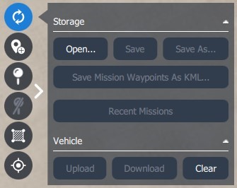
The Plan Tools offer quick access to essential items for planning autonomous missions, such as adding waypoints, inserting survey or scan patterns, and saving, loading, uploading, or downloading mission plans.
Clicking the arrow opens the sidebar, revealing the title next to each icon.
Only valid options are enabled (e.g., Download is grayed out if there is no mission on the vehicle).
Open...
Open a plan file from storage or clear the current mission in the Ground Control Station. This will not affect the plan on the vehicle.
Save
Save previously opened or saved plans under the same name.
Save as...
Save the current plan under a new name.
Save Mission Waypoints as KML ...
Save the current mission as a KML file, which is used by Google Earth.
Recent Missions
Open a menu to access recently created or loaded mission plans.
Upload
Upload the mission plan to the vehicle. Existing plans on the vehicle are cleared.
Download
Download the current plan from the vehicle. The current plan on the Ground Control Station is cleared.
Clear
Clear the mission plan on the Vehicle and AMC. Disabled if no vehicle is connected.
Mission
Center or zoom the map to include all mission waypoints.
All items
Center or zoom the map to include all plan items (missions, geofences, rally points)
Launch
Center the map at the point where the vehicle arms and takes off.
Vehicle
Center the map on the vehicle location. Disabled if no vehicle is connected.
Your Location
Center the map on the location of the Ground Control Station (AMC). Disabled if Ground Control Station does not have location or GPS.
Specified Location
Center the map on a specified location.
Enter geographic, UTM, or MGRS position information, to make it the new map center.
Under AMC`s Top Bar, the Mission Statistics are displayed.
The Mission Statistics give information about the Total Mission Distance, the Maximum Telemetry Distance, and the Total Mission Time.
The Upload Button uploads the current mission to the vehicle. It appears at the top of the screen when a new item has been added to the mission that hasn't been uploaded yet. The button disappears once the upload is complete and reappears when a new unsaved item is added to the mission.
The Mission Editor on the right side enables the operator to adjust the settings of mission items.
The settings are organized into four sections, each focusing on a specific aspect of the mission:
Start: In this tab, you can edit the values of the Mission Start Action, which consists of the Start and Transition Direction items.
Mission: The Mission tab allows you to edit and change the Waypoint commands and provides access to a list of all Waypoint items.
End: In this tab, you can edit the values of the Mission End Action. The Mission End Action can be an Orbit Land Pattern, a Straight Land Pattern, or a Loiter.
Extras: In this tab, you can add or remove GeoFence definitions and select the current GeoFence region for editing on the map.
The distance between two points can be measured, or the area can be calculated as a selectable polygon. Selecting Clear All will delete all Measurement Tools on the map.
Coordinates can be entered manually, and specific points can be removed.
The Terrain Altitude Indicator is located at the bottom of the screen.
A red line indicates a Ground Collision!
In the upper left corner of the Terrain Altitude Indicator, you can choose from three different altitude measurements.
Simply tap the letters next to the three dots to switch between the different altitude measurements:
HGT
Height (Heights are referenced to the takeoff location)
MSL
Mean Sea Level (Altitude Above Mean Sea Level)
AGL
Above Ground Level (Altitude Above Ground Level)
This section discusses the options available in the Vehicle Overview and its sub-menus.
The Vehicle Overview can be accessed via the AMC menuor by clicking the Vehicle Status Indicator.
The Notifications window provides in-flight information for pilots. A more detailed log is uploaded to the Auterion Suite for analysis if the cloud functionality is enabled.
Notifications can be deleted by clicking on the trash bin in the lower right corner of the window.
The Sensors tab provides access to all sensors and their calibration screens. The DeltaQuad Evo's sensors come pre-calibrated, no additional calibration is needed. In some cases, a Compass Calibration may be required. For more information about Compass Calibration, please read here.
Do not attempt to calibrate any of the available sensors except the Compass when indicated. DO NOT perform a Factory reset, as this will render your vehicle unusable.
The Wi-Fi connection is used to establish a wireless link to the flight controller. It facilitates Vehicle Activation and enables minor background updates for the software running on the DeltaQuad Evo.
Hotspot Mode (Default): The flight controller creates a Wi-Fi access point (Hotspot) that a device can connect to for Wi-Fi telemetry. The default SSID (Network) is: skynode-<serialnumber>.
Station Mode (Disable Hotspot Mode): The flight controller automatically connects to an existing local Wi-Fi network using the supplied credentials. If this Wi-Fi network also provides internet access, the vehicle will connect to the Auterion Suite.
Wi-Fi: Select to enable Wi-Fi.
Hotspot Mode: Select to enable Hotspot mode.
Network (SSID): skynode-<serialnumber> (default)
Password: 1234567890 (default)
Status:
Green: Connected
Red: Disconnected
Reset to Hotspot: Resets credentials to the default Hotspot settings.
Connect: Connects to the selected Wi-Fi network.
When Hotspot mode is disabled, the vehicle attempts to connect to the selected Wi-Fi network. Network credentials can be entered in the respective Network and Password fields.
The options presented in this menu are:
LTE: Select to enable LTE connectivity.
APN (Access Point Name): The APN name for your cellular data plan, which depends on your service provider.
Allow Roaming: Select to enable roaming if you want to allow connections to a cellular network that is not your primary service provider.
Enable PIN: Select to use a SIM card PIN. Note that the PIN is not stored and must be entered on every boot when enabled.
Status:
Green - Connected
Red - Disconnected
Submit: Confirm changes.
The DeltaQuad Evo comes with a pre-installed Orange (US, Canada, Europe) SIM card, with a data limit of 10 GB. Additional data can be purchased through Auterion. Alternatively, a SIM card from a local provider can be installed and used with the associated APN.
The table below lists typical Access Point Names (APNs) for existing DeltaQuad Evo users. If your carrier is not listed, please contact their support or check their website to obtain the correct settings.
Orange (global)
orange.m2m.spec
T-Mobile (US)
fast.t-mobile.com
AT&T (US)
NXTGENPHONE
Verizon (US)
vzwinternet
Bell (CAN)
pda.bell.ca
Telus (CAN)
sp.telus.com
Rogers (CAN)
ltemobile.apn
Freedom Mobile (CAN)
internet.freedommobile.ca
Digitalrepublic (CH)
dr.m2m.ch
Sunrise (CH)
internet
LTE must be enabled for VPN Link functionality.
The Active Tasks window is an interface that displays ongoing activities, which is particularly important when conducting surveys. After touchdown, the photos and collected metadata are processed.
The interactive Preflight Checklist in AMC can be accessed by clicking the icon in the lower-left corner of the Vehicle Overview window. This checklist must be completed before every flight, as it is an integral part of the Pre-flight Checks outlined in this manual.
The Safety page is used to configure the most important failsafe settings. To access these settings, click on the Safety icon at the bottom of the Vehicle Overview window.
Read here to learn more about the Safety Features and failsafe settings.
Auterion Suite provides advanced connected vehicle features for the DeltaQuad Evo. To access these settings, click on the Cloud icon at the bottom of the Vehicle Overview window.
Current Features Offered
Live Telemetry: View the vehicle's position and status on a live map.
Live Video: Watch a live video feed from the connected camera.
Picture Upload: Automatically upload all photos taken during a flight.
Getting Started
Before using these connected features, each vehicle must be registered with the Auterion Suite.
Prerequisites
Ensure the vehicle is connected to a network, either via cellular or an internet-enabled Wi-Fi connection.
Wi-Fi Setup from AMC
Connect your computer or device to the vehicle via USB-C.
Navigate to the vehicle's dashboard by visiting http://10.41.1.1 in your web browser and enable features.
Once the features are enabled in the vehicle's dashboard, the cloud options available in AMC can be configured.
The More tab provides access to GPS Advanced Settings and the About tab.
To access GPS Advanced Settings, click the More icon in the lower-right corner of the Vehicle Overview window.
These settings are intended for intermediate pilots and apply specifically to GPS-Denied Operations. For more information about GPS-denied Operations, please refer to the Advanced Flight section in this manual.
The following three settings can be toggled on or off:
Enable this setting to display the vehicle's raw GPS location (indicated by a gray arrow) on the map, toggle GPS Fusion on or off, and manually reset the vehicle's position.
Permit takeoff without a GPS lock.
Enable this setting to manually set the vehicle's Home Position.
The About tab displays information about the software versions.
This section provides an overview of the Advanced tab and the items relevant to the operator.
The Advanced tab can be accessed via the AMC menu.
The first tab is the Summary menu, which displays the vehicle settings. The tabs on the left side are the menus for configuring each of the displayed components.
These settings and menus are not relevant for typical drone operators and should not be changed by end users, except when instructed.
The Storage Setup is crucial for missions where the collected data must remain confidential under all circumstances.
For more information about recording Flight Logs and the available options to disable log recording, please read here.
In the Parameters tab, you can apply under-the-hood changes to the vehicle settings. This is relevant only for special operations that fall outside the standard user profile, such as Offshore or GPS-denied Operations. For more information on which parameters can be changed, please refer to the Advanced Flight chapter.
The following section outlines the options available in the Controller tab.
The Controller tab can be accessed via the AMC menu.
The DeltaQuad Evo Tactical Edition does not utilize a traditional radio controller. Instead, the DeltaQuad Evo handheld controller functions as a joystick. Consequently, all controller settings can be configured under the Joystick tab. The Radio tab is irrelevant for the DeltaQuad Evo Tactical.
The DeltaQuad Evo handheld controller comes pre-configured and works as a plug-and-play device. For more information about stick and button assignments, please read here.
Changing the settings in the Joystick tab is recommended only for experienced operators with sufficient knowledge of the subject matter.
To verify stick input and assign actions to controller buttons, ensure the handheld controller is connected to the Toughbook. Both the GCS and the vehicle must also be powered on and connected.
In the General tab, the joystick can be enabled, and the stick input can be verified by moving the controller sticks.
In the Button Assignment tab, commands can be applied to the available buttons on the handheld controller. When you press a button on the controller, the corresponding field will light up, and an action can be assigned.
Actions or commands will be executed immediately upon being triggered by the controller buttons. Assign actions to the controller buttons with caution, as commands like Emergency Shutdown are irreversible. When triggered in mid-air, a crash is imminent.
By default, only the controller's shoulder buttons are assigned for the zoom functionality of the ISR payloads.
If required, the controller sticks can be calibrated. After clicking Start, you will be guided through the process.
The Settings tab provides additional options for configuring the controller. We recommend leaving these settings at their default values. These options may become relevant when using a traditional remote controller as a USB input device.
Clicking the Flight Tools button in the lower-left corner of the screen will open an extra set of commands for controlling the vehicle. When the button is blue, it is active, and the additional commands will be visible. When the button is gray, it is inactive, and the extra commands will be hidden.
Depending on the payload, a Point of Interest can be set. The camera (gimbal) will follow the specified location while the vehicle remains on its flight path. The Point of Interest can be removed by clicking on Cancel PIO:
Clicking the Map Tools button in the lower-left corner of the screen opens the Map Tools. When the button is blue, it is active, and an extra set of commands will be visible. When the button is grey, it is inactive, and the extra commands will be hidden.
The Marker Tool can be used to increase situational awareness. The set markers will also be displayed in the video feed. When clicking on the Marker Tool button, a menu will open.
The Measurement Tool button opens a menu.
You can switch between the two views by clicking on the AMC Menu icon.
The Plan Tools provide quick access to essential features for planning autonomous missions, such as adding waypoints, inserting survey or scan patterns, and saving, loading, uploading, or downloading mission plans.
Select the Waypoint Tool to enable adding new waypoints to the map.
Select the Point Of Interest (POI) Tool to enable adding a point of interest on the map. The camera gimbal will point toward the last POI created.
Select the Cancel POI Tool to cancel the last point of interest on the map.
Select the Pattern Tool to add or load a Survey or Corridor pattern. Additionally, a KML/SHP file can be loaded.
The Center Tool gives multiple options to center the map.
The Measurement Tool button opens a menu.
The Terrain Altitude Indicator is used to ensure that the mission is set above ground level. It can be toggled to be visible or hidden using the button (Terrain) next to the Measurement Tool.
The following section explains how to log in to your User Account in AMC.
The User Account tab can be accessed via the AMC menu.
Pilots can log into their Suite account directly from AMC, enabling automatic tracking of flight hours in the Auterion Suite. Utilizing the Auterion cloud service is a prerequisite.
When logging in or out you'll be directed to your default browser.
Log in to your Auterion account.
Authorize access to Mission Control if prompted.
Open Mission Control (it should now display you as logged in).
You’re now successfully logged in!
The following section outlines the options available in the Settings menu.
The Settings menu can be accessed via the AMC menu.
The General Settings serve as the primary location for application-level configuration. Configurable options include display units, miscellaneous settings, fly view settings, plan view settings, and storage. These values can be adjusted even when no vehicle is connected. Settings that require a vehicle restart are indicated in the user interface.
The following list outlines the most frequently used settings for day-to-day operations.
Units
Switches between the metric and imperial systems.
Miscellaneous
Color Scheme: Switches between Indoor and Outdoor color profiles.
UI Scaling: Adjusts the scaling of the user interface.
Always Start AMC in Advanced Mode: Ensures AMC opens in Advanced Mode by default.
Fly View
Use Preflight Checklist: Enforces the interactive Preflight Checklist.
Enable Terrain Collision Checks: Keep this enabled for safety!
Display MGRS Coordinates: Toggles MGRS coordinates; when disabled, the Lat-Lon decimal system is active.
Altitude Mode (HGT/MSL/AGL): By default, set to HGT, which measures altitude relative to the Home Location.
Guided Minimum/Maximum Altitude: Affects the values displayed on the Altitude Slider in Fly View when adjusting altitude.
Guided Maximum Distance: Indicates the maximum orbital distance relative to the vehicle's location.
Plan View
Default Waypoints Altitude: Sets the default altitude for waypoints, which can also be adjusted in the Plan View.
Waypoints Maximum Altitude: Specifies the maximum waypoint altitude, typically set to the altitude ceiling permitted by laws and regulations.
VTOL Transition Distance: Defines the distance at which the vehicle transitions from multirotor mode (Hover) to fixed-wing mode (Aero).
Missions Do Not Require Takeoff Item: Important for quick takeoffs, mission planning, and uploading in mid-air.
Display Simulated Path During Mission Planning: A helpful tool that simulates the flight path of the Evo based on the programmed mission items.
Enable Mission Cloud Sync: When utilizing Auterion’s cloud features, mission plans can be synchronized with the Auterion Suite.
Telemetry Logs from Vehicle
Save Log After Each Flight: Basic telemetry logging in AMC is enabled by default. To disable it, uncheck the checkbox. This setting is relevant for missions where no telemetry data should be recorded, not even on the GCS.
Team Awareness
This menu is necessary for setting up ATAK. For more information, please read here.
The Comm Links feature enables you to manually create and connect to communication links. To add a new Comm Link, simply click the Add button. This menu is relevant when connecting a Secondary Control Terminal or when connecting to the Auterion Suite to use the simulator.
This feature allows you to cache maps for offline use.
At the bottom of the screen, options to import and export map data are available. Options provide additional caching choices and allow you to enter the Mapbox Access Token.
When you select Add New Set at the top of the screen, you can choose map tiles for download.
On the right side of the screen, options for Name, Map Type, Elevation Profile, and Zoom Levels are available. After making your selections, the Tile Count and Estimated Size (storage) are displayed. Click Download to commence the download.
In the Maps & Terrain tab, you will find three submenus:
Third-PartyThird Party Licensing: Enter your personal access token for maps.
Imagery: Customize your map provider and map type, and set custom imagery.
Terrain: Select an elevation provider.
These settings and menus are generally not relevant for typical drone operators and should not be modified by end users unless specifically instructed.
The following section provides an overview of the sub-menus within the Analyze tab."
The Analyze tab can be accessed via the AMC menu.
The Log Download tab allows for manual log file downloads. For more information on how to manually download the log files, please read here.
The GeoTag Images tab is not relevant for the DeltaQuad Evo Tactical Edition, as it withholds geolocation data by default. Therefore, mapping payloads such as the Sony A7R Mark 4 cannot be operated with the DeltaQuad Evo Tactical.
The MAVLink Console and MAVLink Inspector menus are not relevant for typical drone operators and should not be modified by end users unless specifically instructed.
This section provides an overview of the Photos menu.
The Photos tab can be accessed via the AMC menu.
In the Photos tab, all snapshots taken during a mission are displayed for easy review.
In the lower-right corner of the screen, two buttons are available for quick access to the storage location of the photos and videos stored on the GCS.
When clicking one of the buttons, a File Manager window opens, displaying the storage location and file path.
Snapshots are always stored directly on the Toughbook. The video storage location can be selected in the ISR payload settings in AMC. The Onboard Storage can be enabled, allowing videos to be stored on a Micro SD card in the ISR payload, or disabled, in which case videos are stored directly on the Toughbook.
The Comm Links menu can be accessed via the AMC menu.
The Offline Maps menu can be accessed via the AMC menu.
The MAVLink and Console menus can be accessed through the AMC menu.


