Loading...
Loading...
Loading...
Loading...
Loading...
Loading...
Loading...
Loading...
Loading...
Loading...
Loading...
Loading...
Loading...
Loading...
Loading...
Loading...
Loading...
Loading...
Loading...
Loading...
Loading...
Loading...
Loading...
A Ground Control Station (GCS) refers to a centralized system or interface that allows operators to communicate with and control unmanned aerial vehicles (UAVs) or drones. The GCS serves as a command center where operators can monitor the drone's telemetry data, receive real-time video feeds from the drone's cameras, and send commands for navigation, flight parameters, and other operational tasks.

The following section gives a basic overview of the DeltaQuad Toughbook and how to connect the handheld controller.
The DeltaQuad Evo TAC comes with the DeltaQuad Toughbook. Auterion Tactical Mission Control comes pre-installed. It provides the communication link between your UAV and the ground systems. The DeltaQuad Military Toughbook is a MIL-STD ruggedized touch-screen laptop. The device is constructed using the Panasonic TOUGHBOOK FZ-55 Touch with a magnesium chassis, flexible configurations, and a universal bay.
To charge the Toughbook please use the provided charging cable.
The handheld controller enables manual override and precision landing.
To connect the handheld controller to the Toughbook, plug the USB connector of the controller to any of the USB ports of the Toughbook.
Number
Type
Function
1
Left joystick
In hover mode
Stick up: climb
Stick down: descend
Stick left: yaw left
Stick right: yaw right
In fixed-wing mode (payload dependent)
Stick up: gimbal up
Stick down: gimbal down
Stick left: gimbal left
Stick right: gimbal right
2
Right joystick
In hover mode
Stick up: move forward
Stick down: move backward
Stick left: move left
Stick right: move right
In fixed-wing mode
Stick up: descend (nose down)
Stick down: climb (nose up)
Stick left: bank left
Stick right: bank right
3
Shoulder buttons L1 and R1
Gimbal zoom for ISR payloads
This chapter covers the command and control features of the vehicle.
This section will discuss how to access the Silvus StreamCaster GUI for optional changes.
All Silvus radios come preconfigured and are ready to use. Changing the settings of the radio is only recommended for advanced users.
Each Silvus radio modem has a dedicated IP address consisting of 4 numbers divided by 3 dots. For example 172.20.123.123. Check your radio modem for the correct IP address.
To get access to the Silvus StreamCaster GUI, the Toughbook must be connected to the Silvus StreamCaster and both units must be powered on.
On the Toughbook open a browser. In the address bar, type in the IP address of the radio modem and press enter.
If you are experiencing any issues with the Google Chrome browser while using the GUI, changing to an “incognito” window may help.
After a few seconds, the browser should open a window with the Silvus StreamCaster GUI. Under the tab Local Radio Configuration -> RF -> Basic, you have access to the basic radio frequency configuration. Here you can set for example the Frequency, Bandwidth, or Total Transmission Power.
To function properly all changes must be applied to both the handheld radio and the DeltaQuad Evo. To save and apply changes to both, ensure that the units are powered on and connected. Choosing 'SAVE AND APPLY TO NETWORK' stores the changes in both devices, preserving them even after a reboot. 'APPLY' only stores the changes until a reboot.
The DeltaQuad Evo Tactical Edition comes with an Interference Avoidance License. When flying in areas where RF jamming is present, the system will use frequency hopping to provide the strongest link possible. The set frequency in the Basic Configuration serves as a starting point from which the system operates.
Under the tab Network Management -> Network Topology, the individual nodes and the signal strength are visible.
Under the tab Security -> Encryption, you can set the security keys.
During setup in our factory, we generate random keys which, for security reasons, are not stored anywhere. When changing the keys, make sure to save and apply the changes to both the handheld radio and the DeltaQuad Evo.
Under the tab Security -> White/Black List a white or black list can be created. A Black List can block specific nodes from the network. A white list can specify the nodes which are allowed to have access to the network.
For further reading and in-depth information, please follow this link.
The following section gives a basic overview of the Silvus StreamCaster 4240-EP and how to assemble it.
The DeltaQuad Evo Tactical Edition comes with the Silvus StreamCaster 4240-EP. The unit consists of a handheld radio modem, two omnidirectional antennas, and a detachable battery.
At the top of the radio modem, you find the following connections:
Connect the two omnidirectional antennas to the RF ports (G).
Connect the battery to the bottom of the radio modem. Align the battery in a 45-degree angle.
Connect both units and turn to align them.
To detach the battery for storage or charging, pull up the battery release latch on the side of the radio modem, and turn the battery until it is released.
The Silvus StreamCaster comes with a breakout cable. Connect the end with one plug to the Primary Port (PRI) of the radio modem.
To properly connect the plug to the socket, ensure that the red dots on both align.
To detach the cable for storage, simply pull the plug out of the PRI socket.
The following section describes the basic assembly and operation of the tripod-mounted sector antenna.
The tripod-mounted sector antenna gives up to 40 km ISR range extension. The horizontal field of view (beamwidth) is 120 degrees and the vertical field of view is 12 degrees. The tripod-mounted sector antenna requires a Silvus StreamCaster 4240-EP for standard operation.
Mount and secure the antenna on the provided tripod.
Connect the double RF antenna cable to the RF ports of the antenna.
Connect the other end of the cable to the RF ports of the Silvus StreamCaster.
Connect the battery to the Silvus StreamCaster as described here.
Connect the Silvus breakout cable to the Silvus StreamCaster and make sure to properly connect the plug to the socket, by aligning the red dots on the plug and the socket.
Mount the Silvus StreamCaster to the tripod with the provided Velcro.
For general information and tips on radio range and line of sight operation, please read here.
The optimal angle for a sector antenna to operate with a drone depends on several factors, including the antenna's beamwidth and the drone's flight path. A sector antenna typically has a directional beam that covers a specific angular range, often referred to as the beamwidth.
The provided tripod-mounted sector antenna has a horizontal beamwidth of 120 degrees and a vertical beamwidth of 12 degrees.
Here are some considerations:
Antenna Beamwidth: Sector antennas have a specified beamwidth. The main lobe of the antenna's radiation pattern is within this beamwidth. Align the antenna so that the main lobe covers the area where the drone is expected to operate most frequently.
Drone Flight Path: Consider the expected flight path of the DeltaQuad Evo GOV. If the drone moves within a specific sector, align the antenna to cover that sector. It's common to point the sector antenna slightly angled upward, depending on the drone's altitude.
Altitude Changes: If the drone is expected to fly at different altitudes, you may need to adjust the tilt of the sector antenna to ensure coverage at varying heights.
Obstructions: Be mindful of any potential obstructions between the antenna and the drone. Adjust the antenna angle to avoid obstacles and maintain a clear line of sight.
Coverage Area: Determine the desired coverage area and adjust the sector antenna angle to match. Sector antennas are often used to cover specific sectors of a 360-degree area.
The following section describes how to establish a connection between the GCS and the DeltaQuad Evo TAC.
Before connecting the GCS to your UAV, the Silvus StreamCaster must be connected to the Toughbook and both items must be switched on.
Plug the Ethernet cable from the Silvus breakout cable into the Ethernet port of the Toughbook.
On top of the Silvus radio modem pull out the rotary knob and set it to 1.
Do NOT set the dial of the rotary knob to Z, as this is resetting the radio to its default settings. This makes the radio unusable.
The Silvus StreamCaster 4240-EP is configured and set up properly in our factory. There is no need for further configuration. The system is plug-and-play ready.
Power on the Toughbook by pressing the on/off button.
Before launching your flight control system it is recommended to connect the Toughbook to a mobile hotspot or Wi-Fi network. The Toughbook uses internet connectivity to load satellite maps and for LTE connectivity to the UAV.
Open Auterion Mission Control (AMC) on the Toughbook. The app shortcut is accessible from the desktop.
During initialization, the GCS and the DeltaQuad Evo establish a connection automatically. The LED on the Silvus radio modem should turn from red to green.
In the upper left corner of AMC, the vehicle status indicator will display a connection to the DeltaQuad Evo. When the indicator is green, the vehicle is ready for takeoff.
The connection between the GCS and the DeltaQuad Evo is established.
This section describes how to control your vehicle using the DeltaQuad Toughbook GCS.
Auterion Mission Control (AMC) is pre-installed on your DeltaQuad Toughbook. This is the main application to control your UAV and the installed payload(s). For further reading, please read the chapter .
When flying a survey mission with a mapping sensor, or using a corridor scan to surveil a border, highway, or river, a full mission with a takeoff item, intermediate waypoints, and a land item can be planned in the Plan View.
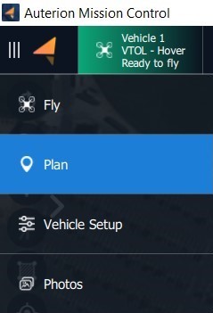
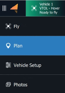
You can switch to the Plan View via the AMC menu.
The mission plan can be executed fully autonomously from takeoff to the landing. It is also possible to take control of the vehicle after the takeoff and initiate a Return command when the mission has ended. The vehicle will use the landing pattern from the mission plan to execute a return command.
For a speedy deployment during a surveillance mission, it might be practical to plan only the takeoff and landing in the Fly View. When starting AMC, the Fly View is displayed. You can choose to plan the takeoff and landing in the Fly View.
Once your mission is uploaded, you can return to the Fly View by pressing the Fly View icon in the left-side command bar.
If the Start Mission button is not displayed, you can press the Action button in the left-side command bar. The Mission Start button will reappear.
When pressing and holding to confirm the takeoff, your vehicle will start its motors and takeoff.
If you created a takeoff and landing in the Fly view, switching views is unnecessary. The vehicle will take off right after pressing and holding the VTOL takeoff button.
When pressing and holding to confirm the takeoff, your vehicle will start its motors and takeoff.
Once the vehicle is launched and has transitioned to fixed-wing flight mode, you can control the flight of your vehicle through the following methods.
While the vehicle is in flight, you can select the Orbit or Fig 8 command from the pilot controls on the left side of the screen.
Tap anywhere on the satellite map to choose the Orbit's or Fig 8's location.
When giving an Orbit or Fig 8 command, the altitude can be changed. A vertical slider will appear on the right side of the screen that allows you to select a new altitude.
After confirming the command by pressing and holding the command button, the vehicle will change course to the set location and adapt to the set altitude.
When the vehicle is following a mission path, it will always track the altitude as defined in the mission plan. When resuming a mission the vehicle will immediately change the altitude to match the currently active waypoint.
The vehicle can be controlled using the right-side joystick.
To activate the joystick control, switch the flight mode to ALTITUDE mode. In the Fly view, click on the Flight mode button in the upper left corner.
A menu with the available flight modes will open, choose Altitude.
In this mode, the vehicle will fly in a straight line at its current altitude until a joystick command is received.
Moving the joystick left or right will make the vehicle change direction.
Moving the joystick forward or backward controls the altitude of the vehicle. A forward (up) joystick movement moves the nose of the vehicle down and decreases altitude. A backward (down) joystick movement pulls the nose of the vehicle up and increases altitude.
If the vehicle loses connection to the DeltaQuad Controller while it is flying in Altitude mode, it will automatically return home, regardless of the Safety settings.
Altitude mode - The DeltaQuad will automatically hold its altitude and direction until changed by the stick input. For flight stabilization and navigation, it will only rely on the IMU and not make use of the compass and GPS.
Position mode - The DeltaQuad will automatically hold its altitude and direction until changed by the stick input. For flight stabilization and navigation, it relies on the IMU and makes use of the compass and GPS.
Under NO circumstances attempt to fly the DeltaQuad Evo in Manual Mode! We do not recommend assigning the Manual Mode to any of the available buttons on the controller.
NOTE: For inexperienced pilots, the joystick controls can seem counterintuitive. It is recommended to practice joystick operation in close proximity while flying at sufficient altitude.
When a mission plan is present, and the vehicle is in ALTITUDE, HOLD, or TARGET FOLLOWING mode, the mission can be resumed by tapping on the ACTION button on the FLY screen and selecting "Continue mission".
Please make sure to disengage the TARGET FOLLOWING mode before returning to MISSION flight mode.
At any point in the flight, the RETURN mode can be activated by tapping on the Return button on the FLY view and holding it to confirm the command.
In RETURN mode, the vehicle will immediately fly towards the landing pattern that was defined in the mission. The landing pattern consists of a circle-to-altitude item, a direction and altitude on which to exit the circle, and a landing coordinate.
When the RETURN mode is activated, the vehicle will fly at its current altitude towards the 'circle to altitude' part of the landing pattern. When reaching this location, the vehicle will circle down to the indicated altitude, and complete the circle until it has reached the indicated exit heading of the circle. It will then proceed toward the landing coordinates, transition to multirotor flight mode, and land in the indicated position.
The multirotor mode should not be used for more than 90 seconds as the system can overheat when utilized longer.
The most common situation where it is practical to use stick control in multirotor mode is during the landing to reposition the Evo if necessary.
This can be achieved by using the NUDGE function.
After the Evo transitioned from fixed-wing mode to multirotor mode, the vehicle will deploy the landing gear and descend to the planned landing point.
The operator can halt the descent by moving the left joystick up.
The Evo will hold its altitude and position. The RIGHT joystick controls the position of the vehicle. Moving this joystick, forward, backward, left, or right changes the position of the vehicle relative to its current heading.
The LEFT joystick controls the vehicle's altitude and heading. Moving the joystick UP will halt the descent. Moving the joystick to its middle position or down will continue the descent. Moving the joystick left or right changes the heading (yaw) of the vehicle.
It is not recommended to fly manually in multirotor mode for longer than 90 seconds.
During takeoff or landing, your vehicle is in multirotor mode. Multirotor mode means the 4 motors for Vertical takeoff and Landing are activated.
To take control of the vehicle in multirotor mode, change the flight mode switch to ALTITUDE mode. In this mode, the vehicle will hold its position and altitude until joystick commands are received.
The LEFT main joystick controls the vehicle's altitude and heading. Moving the joystick UP will increase the altitude. Moving the joystick down will decrease the altitude. Moving the joystick left or right changes the heading (yaw) of the vehicle.
The RIGHT joystick controls the position of the vehicle. Moving this joystick, forward, backward, left, or right changes the position of the vehicle relative to its current heading.
To connect the GCS to the DeltaQuad Evo GOV please continue reading .
Switch on the DeltaQuad Evo. Follow the steps described in the chapter .
Please review the chapter for detailed information on how to plan a mission.
Once you have performed the , you can start the mission by pressing and holding the Start Mission button.
Line of sight (LOS) is a crucial consideration for drone radio systems, as it directly impacts communication reliability and performance.
Line of sight refers to the unobstructed path between two points, such as between a drone and its remote control or between two communication devices. Maintaining a clear line of sight is essential for reliable communication regarding radio systems on drones.
Signal Strength:
Radio signals, including those used for drone communication, travel in straight lines. Any obstacles, like buildings or trees, can weaken or disrupt the signal.
LOS minimizes signal interference, ensuring a strong and stable connection between the drone and the remote control.
Reliability and Stability:
A clear line of sight enhances the reliability of communication. This is particularly crucial for real-time control of drones, where a delay or loss of signal could lead to accidents or loss of the drone.
Range Limitations:
The effective range of radio signals is limited. Maintaining LOS allows the drone to operate within its specified range, ensuring that commands from the remote control reach the drone and vice versa.
Physical Obstacles:
Buildings, hills, and other physical structures can obstruct the line of sight. It's essential to fly the drone in areas with minimal obstructions for optimal communication.
Environmental Conditions:
Weather conditions, such as heavy rain, fog, or snow, can also affect LOS. In adverse weather, LOS may decrease, leading to potential communication issues.
Frequency and Wavelength:
The frequency of the radio signal used by the drone affects its ability to penetrate obstacles. Higher frequencies may have more difficulty passing through obstacles, emphasizing the need for LOS.
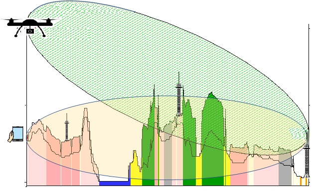
The Fresnel zone, in the context of drone radio systems, is a critical concept related to the propagation of radio waves between the transmitter (typically the remote control) and the receiver (the drone). It plays a significant role in ensuring reliable communication by accounting for potential obstacles that might impact the signal's path.
Key points about the Fresnel zone in drone radio systems:
Elliptical Zone:
The Fresnel zone is an elliptical region that surrounds the direct line of sight (LOS) between the transmitter and the receiver. It extends both horizontally and vertically, forming an elongated shape.
Importance for Signal Propagation:
The Fresnel zone is crucial because it represents the area through which radio waves travel as they propagate between the transmitter and the receiver. An obstruction within this zone can cause signal diffraction, leading to signal weakening or disruption.
Factors Influencing Fresnel Zone:
The size of the Fresnel zone depends on several factors, including the distance between the transmitter and receiver, the frequency of the radio signal, and the terrain along the path.
Clearance for Unobstructed Signal:
For optimal signal strength and reliability, it is essential to ensure that the Fresnel zone is relatively free of obstructions. Obstacles within this zone, such as buildings, trees, or hills, can cause signal degradation.
Interference Avoidance:
Understanding the Fresnel zone is crucial for avoiding interference from obstacles and maintaining a robust communication link between the drone and the remote control. Interference can lead to signal loss, reduced control range, and potential safety hazards.
Choose Open Spaces:
Fly drones in open areas with fewer obstructions to ensure a clear line of sight.
Monitor Environmental Conditions:
Be aware of weather conditions that could impact LOS. Avoid flying in heavy rain or foggy weather.
Adhere to local regulations that may require maintaining visual line of sight with the drone. These regulations are often in place to ensure safety and prevent accidents.
In summary, maintaining a clear line of sight is crucial for the effective operation of radio systems on drones. It ensures reliable communication, stable control, and compliance with regulations, contributing to a safer and more efficient drone flight experience.
The following section describes how to change the encryption of the Silvus radio network.
This guide will help you configure the Silvus radios' encryption in the DeltaQuad Evo Government (GOV) Edition according to your needs. These steps ensure secure communication and protect your data from unauthorized access and cyber threats.
The Silvus radio in the DeltaQuad Evo GOV is set up with encryption by default. DeltaQuad uses randomized encryption keys that are not written down anywhere. It is the operator's responsibility to change the radio encryption to meet the specific requirements of the operation.
Encryption is essential for securing the data transmitted between drones and ground stations. It ensures that sensitive information, such as video feeds and control commands, is protected from unauthorized access. By using encryption, you can prevent cyber threats, eavesdropping, and tampering, thereby maintaining the integrity and confidentiality of your communications.
Silvus radios support several encryption protocols, which vary in the level of security they provide:
AES 56-bit
AES 128-bit
AES 256-bit
These protocols use Advanced Encryption Standard (AES), with higher bit numbers offering stronger security. AES 256, for instance, is highly recommended for the highest level of security.
Access the Configuration Interface:
Connect to the Silvus radio through a web browser using the radio's IP address. A connection guide can be found here.
Navigate to the Security Settings:
Locate the security settings tab and click on encryption.
Select the Encryption Protocol:
Choose the desired AES encryption level (56, 128, or 256-bit) from the dropdown menu or selection box.
Generate a Wrapping and HMAC key and input Encryption key:
Click on the respective fields to generate a Wrapping and HMAC key. The system does not store these keys for security reasons. They are randomly generated based on the chosen encryption method.
Click on the field to input the Encryption key. Enter your encryption key, ensuring it meets the protocol requirements for length and complexity. The system does not store this key for security reasons.
Save and Apply Settings:
After configuring the encryption settings, ensure that you save and apply these settings not only on the device you are currently configuring but also across the entire network. This means applying and saving the settings for all radios, both ground and air units, to ensure uniform encryption across all communication links.
Testing and Verification:
Perform a communication test to ensure that the encryption is working correctly. Verify that data transmission is secure and that there are no connectivity issues.
Additional Considerations
Random Key Generation: The system can generate random keys based on the encryption method, enhancing security by preventing predictable patterns.
Non-Storage of Keys: For cybersecurity, encryption keys are not stored. This practice mitigates the risk of unauthorized access to the keys.
Regularly update and manage encryption settings to adapt to evolving security needs and maintain robust protection against cyber threats.
The DeltaQuad EVO uses Auterion Mission Control (AMC) as its primary Ground Control Station (GCS). The Ground Control Station consists of buttons and has been optimized for use with touchscreen devices.
If you have ordered a Ground Control Station with your DeltaQuad EVO it will have been installed and tested before it was shipped to you.
To install Auterion Mission Control on a separate device such as a laptop or desktop computer, please refer to the . After a successful installation make sure to follow the .
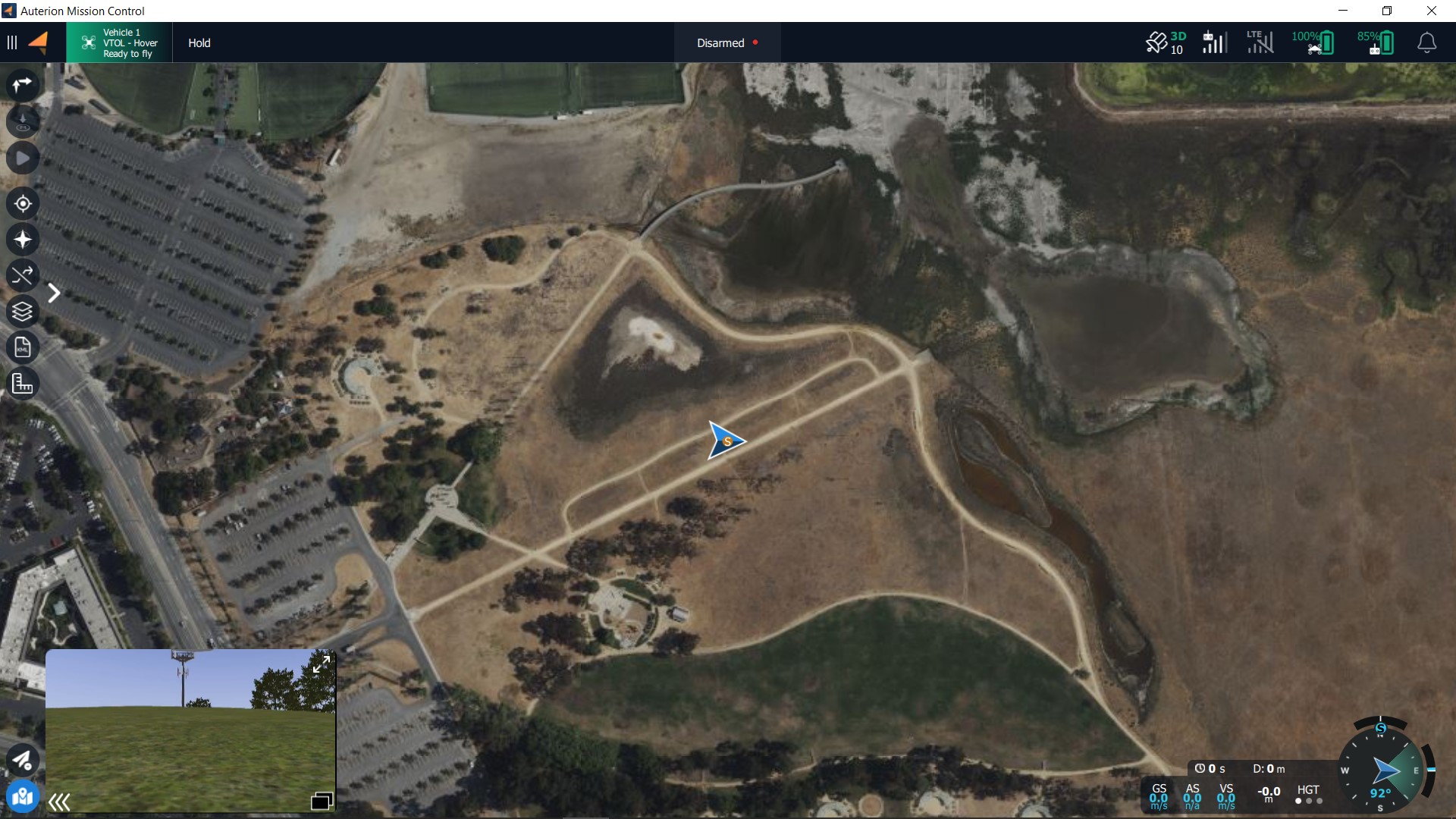
When starting Auterion Mission Control by default the Fly View will be selected.
The application drop-down menu will open. The blue colored tab is the active view. To switch to the other view simply click on the respective tab.
The application menu has four more tabs to choose from.
The following section describes how to connect and set up an ATAK device.
ATAK stands for Android Team Awareness Kit. It is a mobile geospatial platform that enables real-time collaboration and communication among teams, particularly in military and emergency response scenarios. ATAK provides a map-based interface on Android devices, allowing users to share location data, mark points of interest, and communicate with team members in the field. It's designed to enhance situational awareness and coordination among team members by leveraging geospatial information in a user-friendly mobile application.
Skynav Tablet
Data-Link
Ethernet Switch
Android device with ATAK installed (Application is available in the Google PlayStore) Connection
Connect the Ground radio to the Ethernet switch.
Connect the tablet/phone running ATAK to the Ethernet switch
Connect the Ethernet switch to the Skynav
Power the Ethernet switch
Scroll down to Team Awareness (Smartphone Integration) section.
Turn on “Enable Team Awareness” and “Enable on startup”. In Fly View, the Team icon will be highlighted in blue, indicating that ATAK functionality is enabled.
Set "Controller Callsign" to "Mission Control".
Set Destination Address to 172.20.255.255.
Set Destination Port to 4242.
Set Destination Protocol to UDP.
Set Incoming Port to 8089.
Set Incoming Protocol to UDP.
Click on the three dots on the top right. A menu will open.
Choose Settings > Network Connections. Click on "Network Connections" in the pop-up window.
Go to the Input/Output Management section and click on "Manage Inputs".
Edit the default connection (click on the pencil icon) and set address to 0.0.0.0.
Tick the advanced options a. Select Input Protocol to UDP. b Set Server Port to 4242. c. Confirm changes
The checkbox next to the default entry must be checked.
Go back to Input/Output Management. Click on "Manage Outputs".
Click on the three dots in the top right and select "Add". a. Set name to "AMC". b . Set address to 172.20.1.1
Tick the advanced options a. Select Input Protocol to UDP. b Set Server Port to 8089. c. Confirm changes
The checkbox next to the AMC entry must be checked.
Click on the video symbol in the top toolbar. Click on the "+" in the menu.
Change type to "rtsp" in the popup-window.
Add 172.20.110.10:8553/stream1
Optionally: Stream can be named (e.g. "Vehicle 1")
Click on "Add". The stream will appear in the left menu.
Make sure to go through AMC-Settings, ATAK-Settings and Video-Settings first.
Connect the vehicle to AMC.
In ATAK, click on the three dots in the top right. A menu will appear. Click on "Settings" and then "Network Connections". A popup will appear. Click on "Network Connections". Check that the Primary IP Address is in the range 172.20.XX.XX. NOTE: If the Primary IP Address is in a different range, disconnect from the WiFi or cellular network.
As soon as the vehicle has GPS-lock, the position as well as the sensor point of interest will appear on the map. NOTE: If the vehicle is on the ground, the sensor point of interest may not be visible.
Click on the video icon and select the stream previously configured in the ATAK configuration.
Select the marker icon in the ATAK top toolbar.
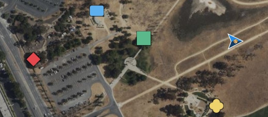
A menu with four different markers will appear on the right side.
Select the desired marker and click on the map to place the marker.
Click on "send" in the bottom right menu. You can either send the marker to a particular device or broadcast it.
The markers will appear in the map in AMC (Fly View only).
Auterion Mission Control offers two main views. In the Fly View, you execute and monitor missions. The Plan View is used to plan autonomous missions for your vehicle. Once the mission is planned and uploaded to the DeltaQuad EVO, you switch to the to perform the and execute the mission.
You can switch between the two views by clicking on the Menu Icon .
The following two chapters will explain in detail the layout of the and the .
There are two modes Auterion Mission Control can run in. The Normal mode and the Advanced mode. When tapping five times on the Menu icon a pop-up window will appear with the option to switch to Advanced mode.
When the Advanced mode is enabled the Menu icon is black.
When the Normal mode is enabled the Menu icon is orange.
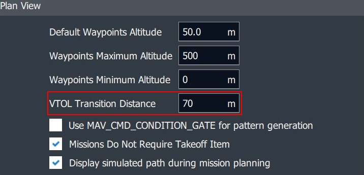
In Advanced mode, more options are available. For example, the Analyse tab in the Auterion Mission Control menu will become available, or the VTOL Transition distance can only be changed when operating in Advanced mode.
When Advanced mode is enabled tapping five times on the Menu icon will open a pop-up window with the option to switch to Normal mode.
Select > Settings > General.
Before executing a mission the following conditions must have been met:
The mission must be planned in accordance with the guidelines set out in Planning a mission.
The Pre-flight checks must have been performed and passed.
The vehicle should be pointing with its nose towards the wind.
All flights must be started with a fully charged battery.
The operator and any observers must keep a safe distance from the vehicle, a 10m minimum is recommended.
When all checks are performed, and everything is set up and working properly, you can start the mission. The mission can be started by sliding the "Start mission" activator.
When the vehicle needs to be returned while executing a mission, the recommended method is to direct the UAV toward a waypoint that will provide a clean entry into the pre-defined landing sequence. You can change the active waypoint that the vehicle is following by clicking the desired waypoint from the fly screen and confirming the change request.
Please note: when changing the active waypoint, the vehicle will immediately change its altitude to the altitude of the selected item. It will not gradually climb or descend but reach the new altitude as fast as possible. It is therefore recommended to select a waypoint that has an altitude at which the vehicle can safely return from its current position. If a waypoint with a safe altitude is not available, it is recommended to first reposition the UAV to a safe location by tapping a location on the map. While repositioning the UAV it will maintain its current altitude.
Using the simulator is recommended to practice returning the UAV during a mission using the method described in this section.
Throughout the mission, both the telemetry data and the vehicle should be monitored. This task can be performed by a single operator, but it is recommended to perform this task with one operator and an observer. The observer should continue to watch the vehicle and its surroundings and alert the operator of any problems or nearby traffic.
Note: It is highly recommended to practice the following exercise in the simulator several times before operating the vehicle.
From the flight screen, and when the vehicle is armed, the following key functions are available:
LAND: Land immediately.
The vehicle will land at its current location. If the vehicle is in Fixed Wing mode the vehicle will transition back to quadcopter mode first.
This button is called "Take off" while on the ground.
RTL: Return To Launch.
The vehicle will return to its takeoff point via the "Landing Pattern" command which consists of the "Loiter" waypoint and the "Land" item.
The vehicle will reach the "Landing Pattern" command in a straight line from its current location at its current altitude. If the current altitude is lower than the Return Home altitude in the Safety settings it will climb to this altitude. If the vehicle is flying in Quadcopter mode it will return to the "Landing Pattern" command and land in this mode. If the vehicle is in Fixed Wing mode it will return as Fixed Wing to the "Landing Pattern" command, perform a back transition when reaching the takeoff location, and land in quadcopter mode.
The advantage of facilitating the "Landing Pattern" command is that it will provide a clean entry into the pre-defined landing sequence and execute the transition and landing into the wind.
Note: using RTL is a last resort. The recommended method of returning the vehicle in fixed-wing mode is described in the section "Returning the vehicle during a mission" above.
PAUSE: The vehicle will hold its current position.
In Fixed Wing mode it will circle the current position with a radius of 100 meters. While in pause mode, when there are no open dialogs, tapping anywhere on the map will give you the ability to select "Goto location".
When sliding to confirm the goto command, the vehicle will proceed to the selected location.
ACTION: The "Action" button.
With the "Action" button the mission can proceed, or the flight altitude can be changed. The "Action" button becomes available when the vehicle is in HOLD mode (pause). See the picture below.
When tapping the action button two options become available.
CONTINUE MISSION will resume the mission towards the next waypoint indicated by a green color. If the option CONTINUE MISSION is not available you can resume the mission by switching to MISSION mode using the "Flight Mode" button.
The minimum and maximum altitudes can be set in the "Application Settings" under the "Q" icon.
Emergency Actions: This button will indicate the current state of the DeltaQuad.
When the vehicle is in flight (armed) this button can be clicked and the option to "Disarm" the vehicle will appear.
When clicking the "Disarm" button the emergency stop box will appear.
When confirming the emergency stop all motors will stop IMMEDIATELY. This procedure should only be used while the vehicle is on the ground or as a last resort to avoid damage to people or property.
Note: Using this function during flight will crash your vehicle and void your warranty.
Land: The vehicle will land at its current location. If the vehicle is in Fixed Wing mode the vehicle will transition back to quadcopter mode first.
FLIGHT MODE: This button displays the current flight mode. By tapping this button a new flight mode can be selected. Supported flight modes are HOLD, RETURN, and MISSION. Switching flight modes using this method will not require slider confirmation. Note: When a new flight mode is selected this will be activated immediately.
VTOL MODE: This button indicates if the vehicle is currently in multi-rotor or fixed-wing mode. Tapping this button will provide the option to switch modes.
At altitudes higher than 100m above ground, or in strong winds, it is not recommended to switch from fixed-wing to multi-rotor mode.
WAYPOINT items:
The waypoint items on the screen can be tapped. When tapped a dialog appears asking if the vehicle should proceed to the selected waypoint. When confirmed the vehicle will proceed in a straight line towards the selected waypoint. It will also immediately change to the altitude of the selected waypoint.
The operator should monitor the following:
The following should be monitored directly after takeoff while the vehicle is ascending vertically to its transition altitude.
Toilet bowling Operator action: LAND The vehicle should take off in a straight line after the first few meters. If the vehicle starts "toilet bowling" (circling up) the mission should be aborted and a sensor calibration must be performed.
Not holding position Operator action: LAND The vehicle should take off in a straight line. If the vehicle starts drifting from its position more than a few meters it should be commanded to LAND. Contact support to have your log files analyzed.
Takeoff failure Operator action: DISARM If the vehicle fails to take off or only one-half of the vehicle rises it is likely that the quadcopter propellers are damaged, mounted incorrectly, or upside down. The operator should disarm the vehicle and review the propeller's configuration as described in the assembly section.
Excessive current draw Operator action: LAND If the current draw indicated by CURRENT from the telemetry display exceeds 180 Amperes the flight should be aborted. The vehicle could be overweight, flying outside of tolerable wind conditions, or has a malfunction. In the case of a malfunction inspect the vehicle for visible damage to the propellers or a higher resistance in any of the motors. If there was no evident damage then contact Vertical Technologies support for analysis.
After reaching transition altitude the vehicle will commence the transition to fixed-wing flight. (switching from quadcopter to fixed wing). It will transition into the direction that the vehicle was placed in, but wind can have an effect on the direction, especially if the vehicle is not positioned with its nose directly into the wind. The vehicle will engage full thrust for 15 seconds using its pusher motor. After this period it should navigate towards the takeoff location or the first waypoint.
No forward motion Operator action: LAND If the vehicle is not moving forward or is drifting with the wind and does not seem to transition towards fixed-wing there is likely a problem with the pusher motor or propeller.
Flying backward Operator action: LAND If the vehicle starts flying backward with increasing speed it is likely to have the pusher propeller mounted in the wrong direction. The transition should be aborted and the pusher motor should be inspected.
High current slow forward flight Operator action: RTL If the vehicle is moving horizontally in the direction of the first waypoint at low speed, with the quadcopter motors still engaged after 15 seconds, and the current draw remains above 30 Amperes, it is likely that the mission did not issue a VTOL TAKEOFF command but a TAKEOFF command. The vehicle will attempt to complete the mission in quadcopter mode. If this was not intended, RTL should be initiated by the operator. Note: The DeltaQuad can activate its pusher motor in quadcopter mode too. The spinning of the pusher motor is no indication that the vehicle is attempting fixed-wing flight.
Switch to multi-rotor mode Operator action: Transition to fixed-wing or LAND There are some conditions where the vehicle can switch to multi-rotor mode. These include loss of positional awareness or accidental mode switching by the operator. In these events, it is usually prudent to attempt to resume fixed-wing flight by pressing the VTOL mode switch (G). If this fails for any reason, the vehicle must be landed. When the vehicle is higher than 200m this must happen immediately as the multirotor mode may consume too much energy to complete a full return.
Abort error displayed due to loss of altitude or maximum bank angle Operator action: LAND This error is displayed on the Ground Control Station when the vehicle has activated the failsafe system. The UAV must be landed as soon as possible. Do not attempt to complete the automatic return sequence if the vehicle is higher than 100m or further than 800m from the home position. If the battery is lower than 35% it should always be landed. Use the map to locate a safe area to land the UAV and direct the UAV to this location. Then press the LAND button to land immediately.
After such an event the cause must be determined before a new flight is attempted. Please contact Vertical Technologies support for assistance in analyzing the cause of the failsafe event.
Excessive altitude loss Operator action: Return or LAND During and shortly after transition, the vehicle may lose some altitude, this is generally not more than 5 meters. In extreme cases (high payload, strong wind). This can be up to 8 meters. The vehicle should recover from this loss quickly, and regain and maintain altitude. Some altitude gain or loss may occur when banking (changing direction). This should not exceed 5 meters.
If the vehicle does not maintain altitude, or if the altitude error exceeds 10m and the vehicle does not recover from this altitude error an RTL should be commanded. If the vehicle does not adequately perform the RTL procedure (continues to lose altitude or fails to navigate back) a LAND instruction should be given. After a LAND instruction is given, and the vehicle is performing a landing in quadcopter mode, the RTL instruction can be given again to have the vehicle return in quadcopter mode. This should only be attempted when the vehicle is less than 1km from the takeoff site and more than 50% of the battery capacity is available.
The reason this can occur could be related to weight, balance, or a problem with the servos or pusher drive. A thorough inspection of the vehicle is required. If the problem can not be found and resolved you should contact Vertical Technologies support.
Failure to track the mission path Operator action: Return or LAND During the transition, the vehicle does not fly in the direction expected:
When the transition phase completes, the vehicle should fly towards its takeoff location or first waypoint. If the vehicle does not follow its intended path after the transition phase, an RTL should be commanded. If the vehicle does not adequately perform the RTL procedure (continues to lose altitude or fails to navigate back) a LAND instruction should be given. After a LAND instruction was given, and the vehicle is commencing a landing in quadcopter mode, the RTL instruction can be given again to have the vehicle return in quadcopter mode. This should only be attempted when the vehicle is less than 1km from the takeoff site and more than 70% of the battery capacity is available.
The reason this can occur can be related to a failure of the servo actuation or if a mission is incorrectly loaded.
Excessive pitch Operator action: Increase cruise throttle / Return The DeltaQuad should cruise at an average pitch angle between 3 and 9 degrees unless a change in altitude is commanded. If the pitch angle consistently exceeds 12 degrees while the vehicle is not attempting to climb to a higher altitude the cruise throttle should be increased. Increasing the cruise throttle can be done by changing the parameters as described in the Key parameters section. This parameter can be changed during flight. If this does not resolve the problem the flight should be aborted by issuing an RTL command. Note: When changing the cruise throttle during flight special care must be taken to monitor the battery level.
The reason for this could be related to sensor calibration, overweight, too low cruise throttle, or a problem with the fixed-wing drive. To resolve this attempt to level the vehicle as described in the sensor calibration section, verify the weight or increase the cruise throttle. If the problem persists please contact Vertical Technologies support.
Battery level and current consumption Operator action: Return The battery level percentage indicated in the top bar of the flight screen should be monitored throughout the flight. the percentage should always be higher than the relative distance the vehicle still has to travel. For example, if only 50% battery remains, more than 50% of the mission should have been completed. The CURRENT and CONSUMED values will also help determine this. The DeltaQuad should draw between 9 and 15 Amperes of current on average during cruise flight. This value increases;
The vehicle is flying significantly above sea level
If the vehicle is flying with maximum payload.
As the battery percentage drops.
When the vehicle is climbing or banking.
When the cruise throttle is set higher.
When the LiPo gets older.
When a power-consuming payload is active.
Ground speed Operator action: Increase cruise throttle The DeltaQuad will generally maintain a constant speed through the air, but wind conditions will impact the effective ground speed. If the ground speed drops below 6 m/s the cruise throttle should be increased. Increasing the cruise throttle can be done by changing the parameters as described in the Key parameters section. This parameter can be changed during flight. Note: When changing the cruise throttle during flight special care must be taken to monitor the battery level.
When this happens the vehicle is likely flying in wind conditions that exceed the specified tolerance.
When the DeltaQuad is flying towards its last waypoint (the VTOL_LAND waypoint) it will determine the appropriate distance from the waypoint to initiate its back transition. The distance depends on the current ground speed and can vary between 5 and 100 meters from the land position. During the back transition, the DeltaQuad will activate its pusher motor in reverse direction to slow down.
Excessive overshoot Operator action: None If the vehicle overshoots its landing waypoint significantly and does not seem to slow down during back transition, there could be a problem with the pusher reverse system. The vehicle should be thoroughly inspected for loose connectors on the flight controller (specifically connectors 7 and 8 as indicated on the wiring diagram). If no problem was found with the connectors the vehicle should be grounded and undergo extended maintenance.
Unstable descent Operator action: None If the vehicle becomes unstable during landing the land speed as indicated in the safety features is likely set too high.
No auto disarm after touch down Operator action: Disarm The DeltaQuad should disarm automatically 5 to 10 seconds after touch down. If the vehicle does not disarm automatically the disarm command (emergency stop) should be sent. This command can be sent by pressing the "Armed" label.
The reason for this could be related to landing on a significantly uneven surface or slope. It can also indicate the sensors need calibration.
Before the mission plan can be created, the following steps should be taken to ensure safe execution:
A mission plan should only be executed after a thorough inspection of the entire mission on site. All altitude differences and obstacles should be known and taken into account.
Missions must be allowed to be executed in accordance with local laws and regulations.
The mission path must be free of obstructions for at least 200 meters in each horizontal direction.
During fixed-wing flight (Aerodynamic mode) the vehicle should stay 50m above ground level, near the end of the mission, to reduce landing energy consumed, an altitude of 25m above ground is recommended.
For maximum endurance a takeoff altitude can be set to 25m, however, to ensure the safety systems can function properly, the takeoff altitude should be at a minimum of 60 meters above ground level.
The takeoff and land sites must consist of a level, flat surface that is free of obstructions for at least 5x5 meters.
The takeoff altitude should be set high enough for the vehicle to be able to perform a transition in any direction.
The weather conditions must fall within the maximum allowed conditions.
Both the front and back transition paths must be planned in such a way that the vehicle is pointing with its nose toward the wind while performing the transition.
The intended mission should not consume more than 85% of the total energy available.
At any point in the mission, the vehicle must be able to return to its takeoff point in a straight line at its current altitude.
At any point in the mission, the vehicle must be able to initiate an unscheduled landing without causing damage to itself or its environment.
Vehicle Setup
Vehicle configuration, including sensor calibration and safety actions.
Photos
View photos and videos downloaded from the vehicle.
User Acount
Login or logout of Auterion account. This associates pilots with flights on Auterion Suite.
Settings
Application Settings
Mission conforms with local laws and regulations.
The mission was planned in accordance with the guidelines set forth in the Plan section.
Altitudes verified across terrain height.
At every stage in the fixed wing portion of the flight, a vertical separation of at least 25 meters above the highest obstacle is maintained.
The mission path is free of obstructions for at least 200 meters in each horizontal direction.
VTOL Takeoff and VTOL Land items were correctly applied.
The takeoff location is free from obstructions at transition altitude for 500m in every direction.
Takeoff and land site are clear of obstacles and structures higher than transition altitude.
The path for takeoff and landing is set so that the vehicle points into the wind.
The vehicle does not exceed the scheduled maintenance or preventive maintenance cycles.
The airframe conforms with all local rules and regulations and is permitted to fly the intended mission.
The propellers are mounted in the correct position, orientation, and direction as specified in the Assembly section.
Visual inspection for damage, dirt, and correctly mounted and securely fastened:
Propellers
Motors
Wings
Servos
Elevons
Devices inside the fuselage
Flight battery
The landing gear is free from ice, snow or mud. This could cause the landing gear to freeze and prevent deployment.
The vehicle is launched from a solid surface that is devoid of snow, or mud.
The pitot tube is free from icing
The batteries are heated above 10 degrees celcius before takeoff.
When the vehicle sits outside, the hatch must not be closed until the vehicle is ready for takeoff as the components inside could overheat when sitting idle. Exposure to direct sunlight when idle for more than 5 minutes should be avoided.
Flight battery - Securely positioned, connector fully joined.
Telemetry - Attached and working.
The payload sits within the payload bay, is properly connected, and does not exceed 3 kg.
Components inside the fuselage are securely fastened and cannot move during flight.
Hatch secured (closing mechanism pushed down and locked)
Hatch sits flush with the fuselage
Wings are properly secured.
The vehicle is pointing into the wind.
No warnings on GCS.
The wing servos are powered (try to move the elevons and feel resistance from the servo).
The vehicle's current physical orientation matches the heading observed on GCS.
The flight battery is fully charged.
The ground equipment has sufficient charge to perform the mission.
Safety features are set correctly.
GPS lock is stable with at least 10 registered satellites.
Mission plan is uploaded
The takeoff waypoint is active (green)
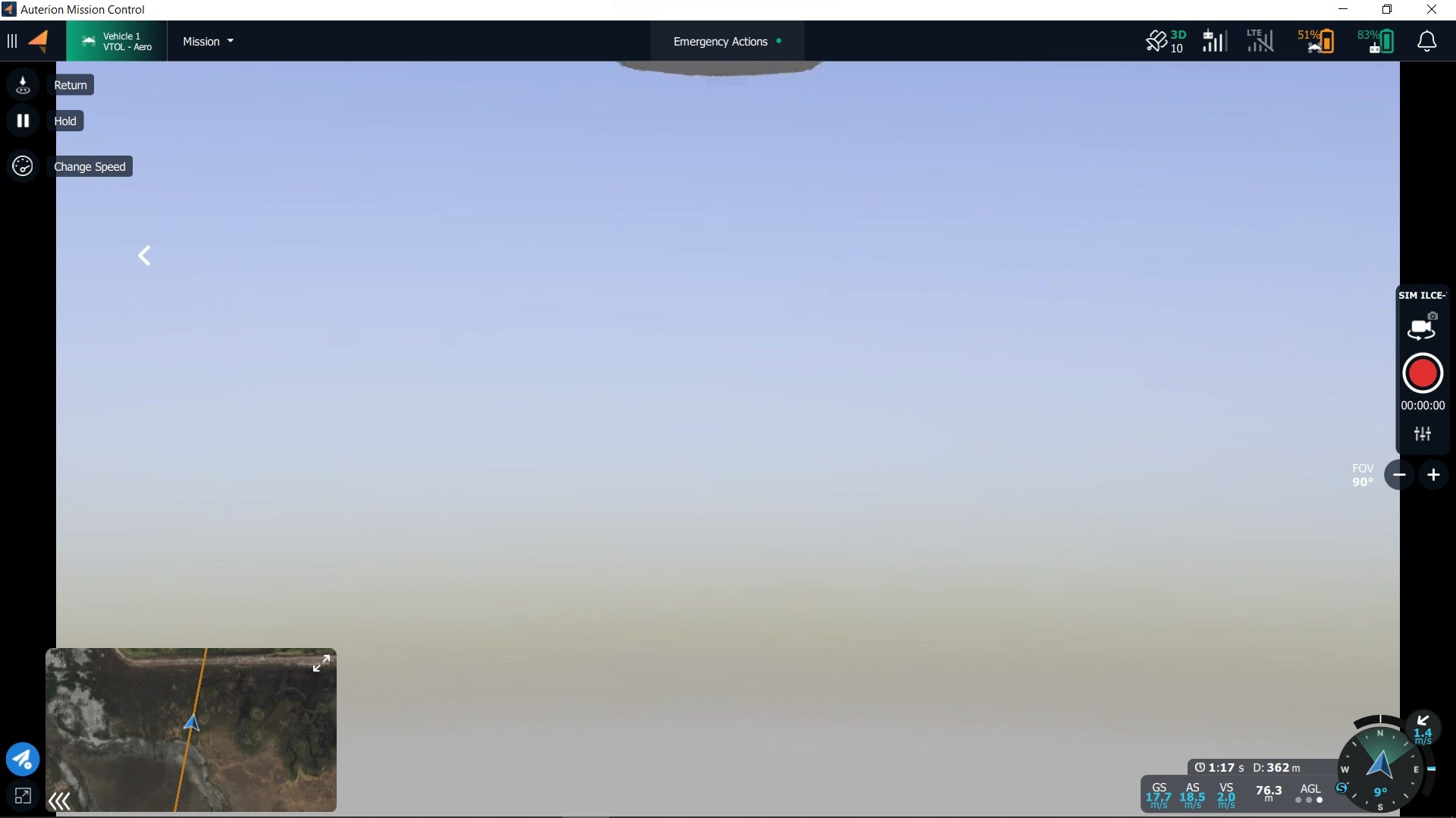
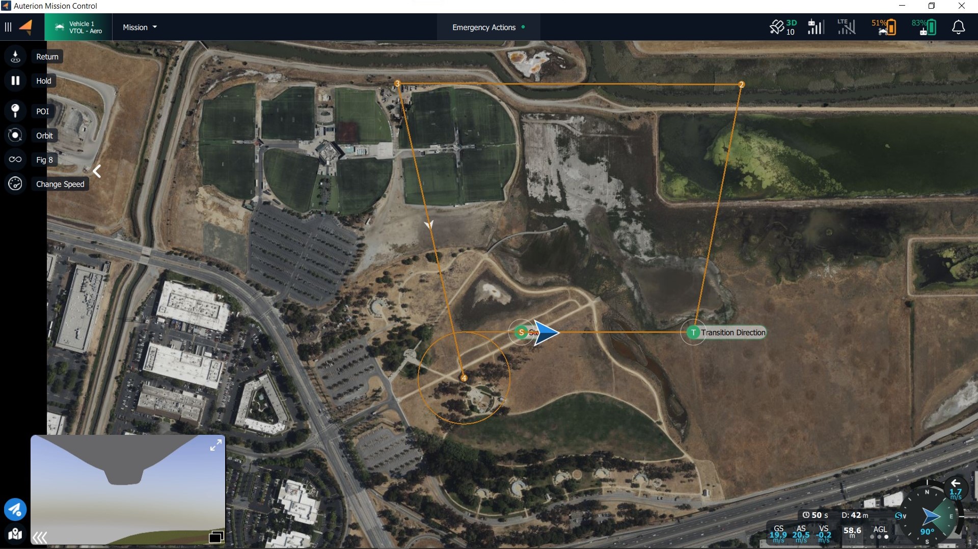
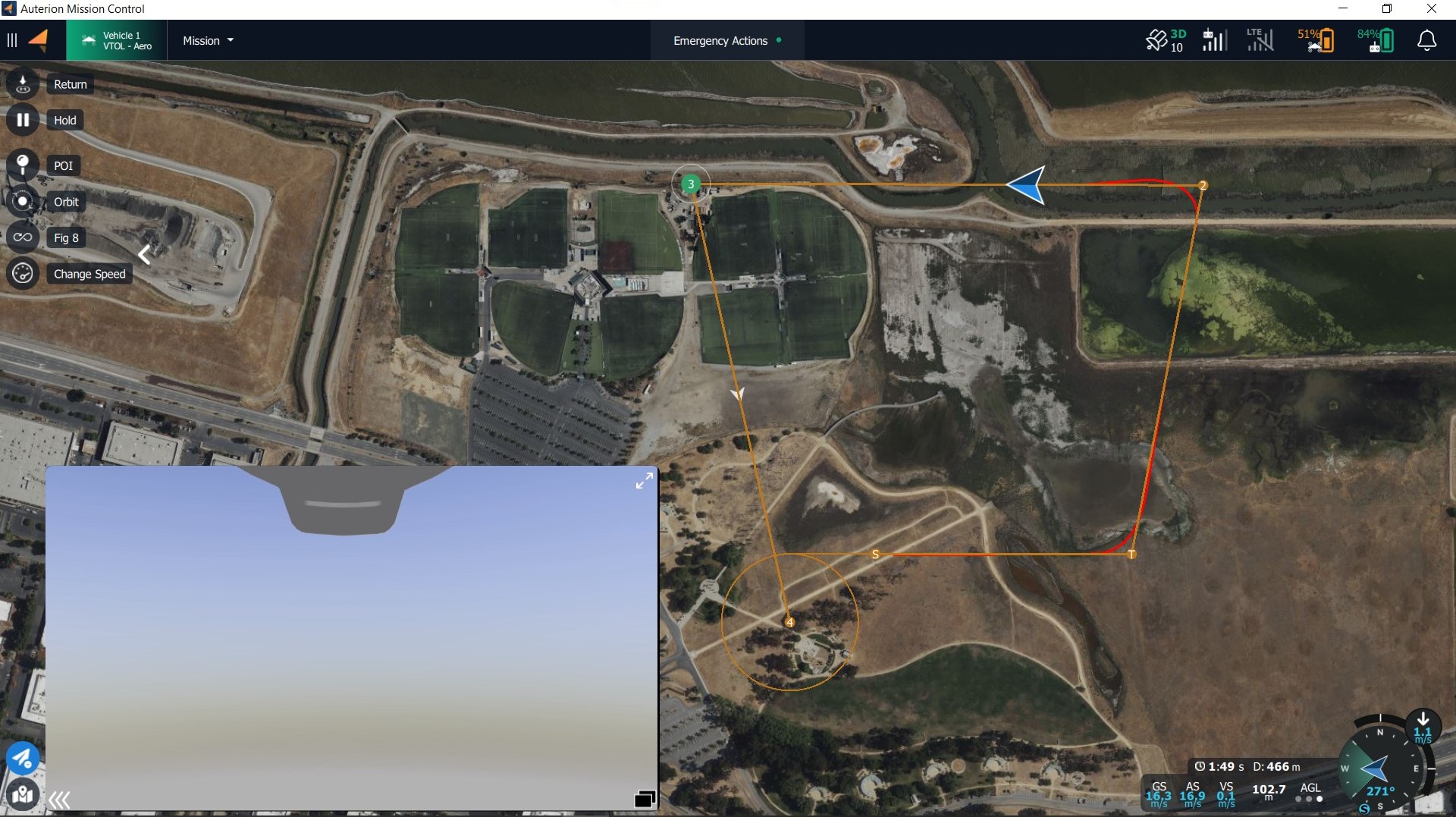
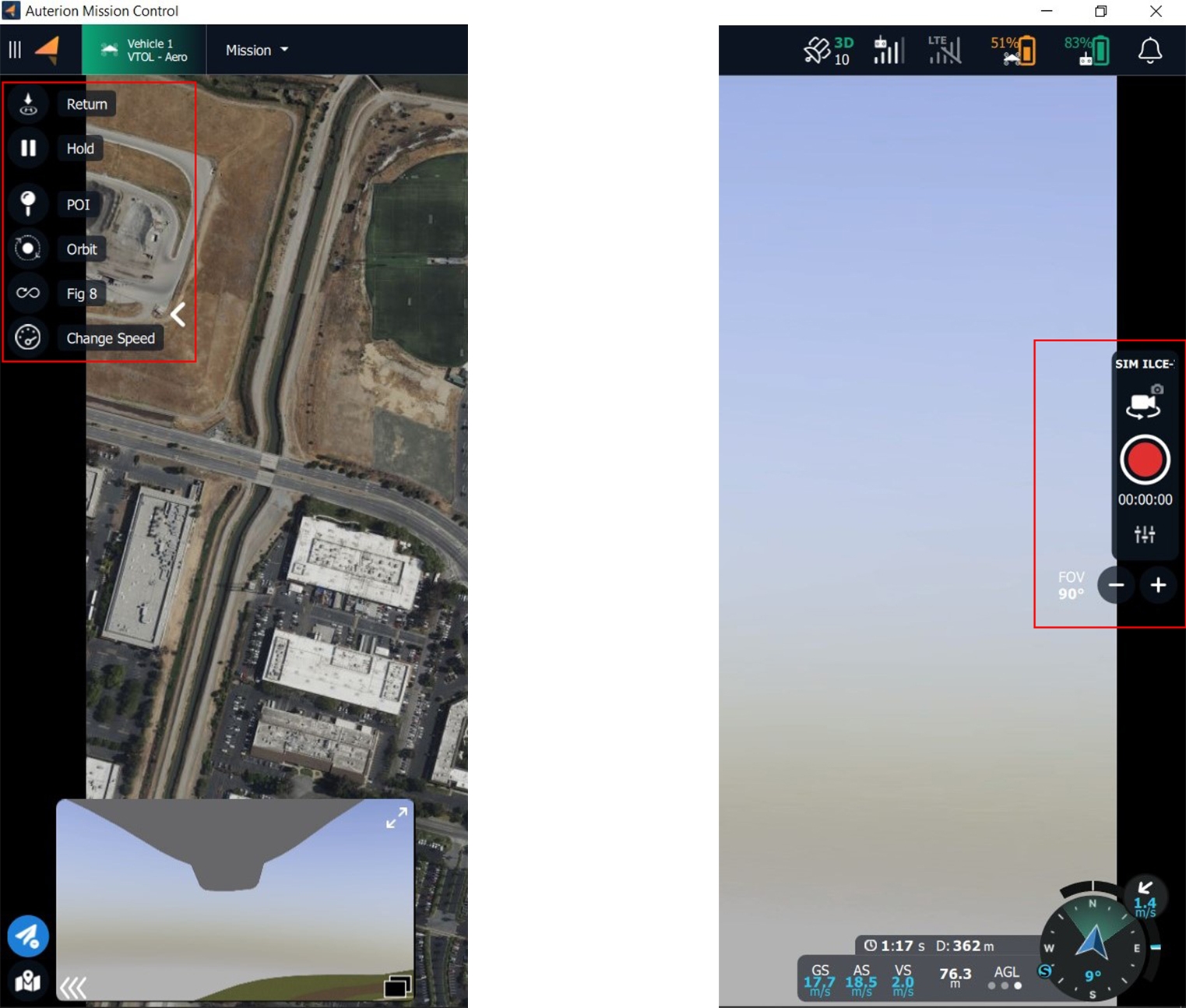
In the Fly View, missions are executed and monitored. The operator has two layouts available. By default, the map is the primary view and the video feed is the secondary view. You can change the layout by clicking the small window in the lower left corner.
Primary view - map, secondary view - video feed:
Primary view - video feed, secondary view - map view:
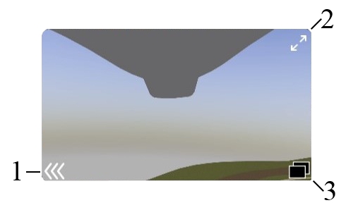
The smaller secondary window in the lower left corner can be resized by clicking the two arrows in the upper right corner. Simply drag the window to the desired size.
The following is a complete list of actions that can be taken within the secondary window.
Minimize or maximize the window
Adjust the size of the window
Detach the window from the lower left corner
Depending on whether the map or the video feed is the primary view, the available tools, and functions change. When the map is the primary view, all Fly Tools are available. When the video feed is the primary view the payload controls are available.
Map is the primary view: Video is the primary view:
All Fly Tools are available Payload controls are available
The available payload controls depend on the mounted payload. The payload controls will be discussed separately in the dedicated section for each available payload.
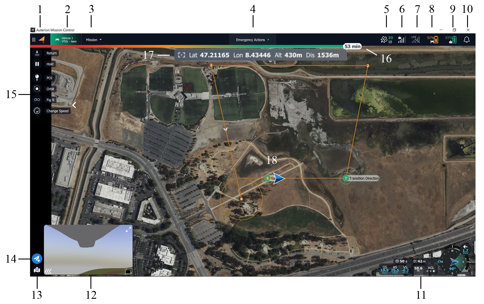
The following list describes all elements of the Fly View.
AMC Menu
Vehicle Status and Selector
Flight Mode
Emergency Actions and Arm Status
GPS Status
Radio Signal Strength
LTE Status and Signal Strength
Battery Status of the Vehicle
Battery Status of the Ground Control Station
Notifications Tab
Telemetry and Compass
Video feed
Map Tools
Flight Tools
Fly View Tools
Estimated flight Time Remaining
Additional information depending on mounted payload
Map, Mission Items, Smart Actions, Vehicle Location (blue arrow), and Vehicle Track (red trail)
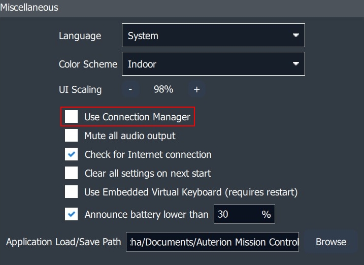
The DeltaQuad EVO does not make use of the Connection Manager. In Settings>General>Miscellanous this option can be disabled.
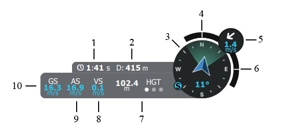
The Telemetry Panel is located in the lower right corner of the screen. It is available in both layouts when the map is the primary view and when the video is the primary view.
Time since armed (approximate flight time)
Distance between vehicle and ground station
Compass (incl. vehicle heading, camera field of view, direction towards the Ground Control Station)
Roll Index
Wind direction and wind speed
Pitch Index
Altitude display - tap the letters above the three dots to change to the different altitude measurements:
HGT
Height above takeoff
MSL
Altitude above Mean Sea Level
AGL
Altitude above Ground Level
Vertical speed
Calibrated airspeed
Ground speed/horizontal speed
The following Fly View Tools are available on the left side of the screen when the map is primary.
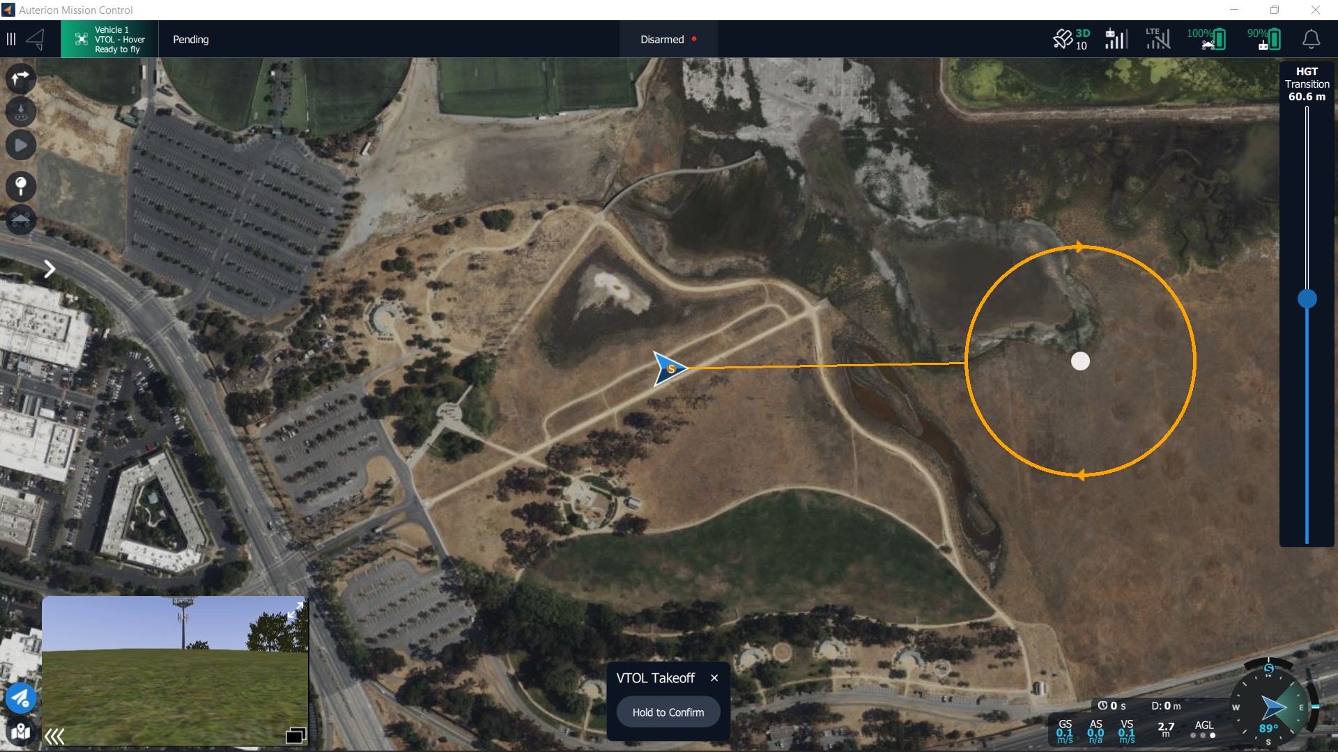
Takeoff
Command for takeoff - altitude, transition direction, loiter for takeoff, and approach sectors can be set.
Return
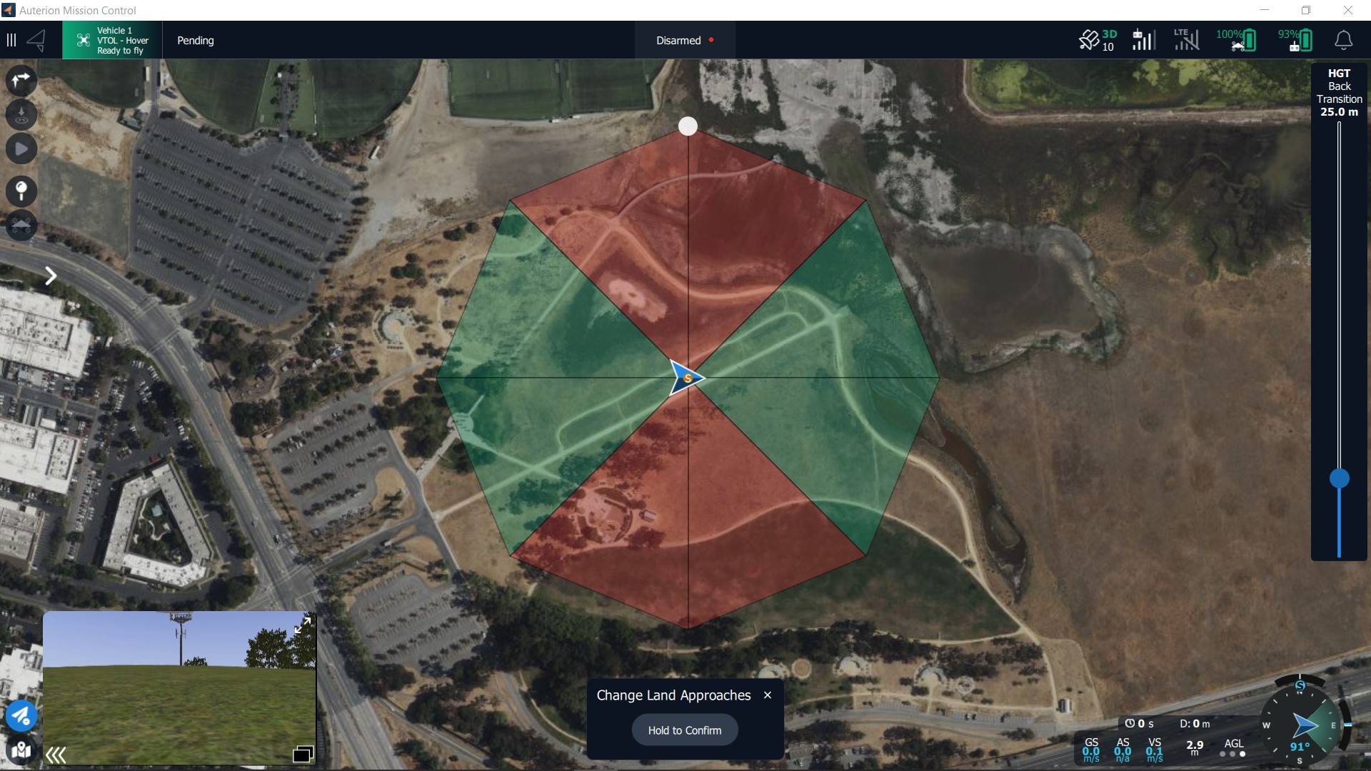
Return to the start location - the vehicle will return with the approach feature if at least one green sector is set. If no green sector is available the planned landing pattern will be ues.
Mission
Starts or resumes the planned mission.
Hold
Pauses the mission or any action. The vehicle will loiter at its current location.
Approach
Approach sector and Safe Areas can be modified.
POI
Orbit
Sets an Orbit with selectable altitude, radius, and loiter direction.
Figure of 8
Sets a figure of 8 with selectable figure size, and altitude. The figure of 8 automatically realigns when a POI is set to keep the POI in the field of view.
Change Airspeed
Enables the operator to change airspeed. When clicked the Airspeed slider appears on the right side of the screen. Values between 14m/s to 25m/s are available.
Set Altitude
The altitude of the vehicle can be changed.
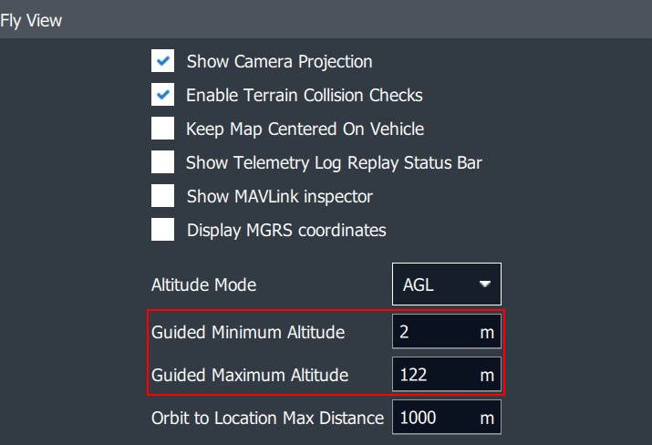
These values can be changed in Settings>General>Fly View.
Center Map
Centers the map on the vehicle
Marker
Set markers for situational awareness
Clear Path
Delete last flightpath to clear the map
Map Layers
Changes between map layers
Load KML overly
Import KML file to the map
Measure
Opens the Measurement Tools
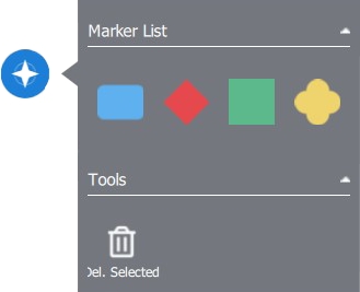
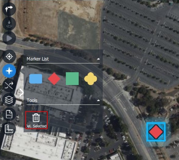
When clicking on the Marker Tool button a menu will open.
Different Marker Tool Categories can be chosen by color and form. Click on the map to set the marker.
To delete a marker, select it on the map and click on Del. Selected in the Marker Tool menu.
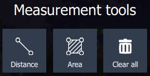
The distance between two points can be measured or the area in the form of a selectable polygon. Clear all will delete all Measurement Tools on the map.
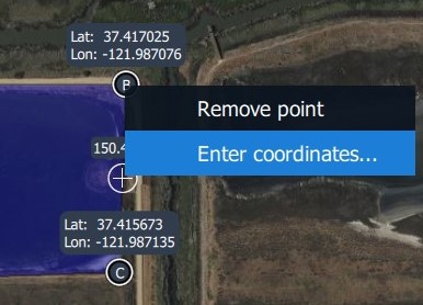
Coordinates can be entered manually.
The third item in the upper-left corner of the screen is the Flight Mode icon.
This item displays the vehicle`s current flight mode. When clicked the operator can change to the Position flight mode for manual control.
During operation, the Flight Mode icon can display the following modes.
VTOL Takeoff
Flight mode during takeoff
Mission
Flight mode in which the vehicle executes a planned mission.
Hold
Flight mode when the Hold, Orbit, or Figure of 8 command is given.
Return
Flight mode when executing the Return command.
Land
Flight mode when Landing in the Emergency Actions has been chosen.
Position
Manual flight mode is enabled. The vehicle can be controlled with the right joystick. When there is no stick input the vehicle maintains altitude and course.
Takeoff in Hover mode and transition to Aerodynamic mode.
Before creating a new mission plan make sure that there are no items such as waypoint commands on the map.
First, enter the Plan view by selecting the Plan tab from the AMC menu.
You can clear all waypoints from AMC and the vehicle by selecting the File Tool from the Plan Tools. Choose the clear option.
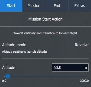
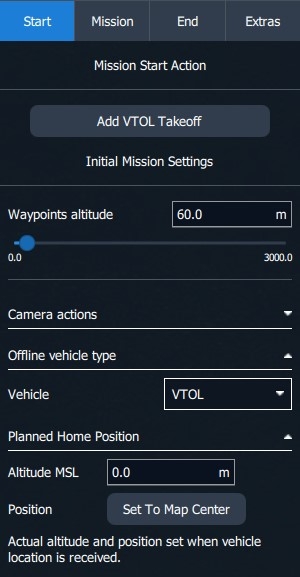
When selecting the Start tab the option Add VTOL Takeoff is available.
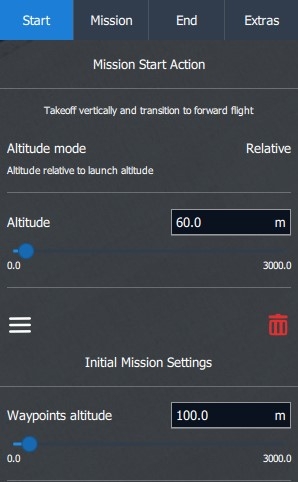
Set the VTOL Takeoff altitude in the Plan Item Editor. This is the altitude at which the vehicle transitions from Hover mode to Aerodynamic mode.
We recommend a minimum VTOL Takeoff altitude of 60m for all safety features to function properly. Always make sure to set an altitude that surpasses the height of all obstacles present between the Start and Transition Direction waypoints.
Please be aware that the altitudes of mission items in the Plan View are relative to the launch altitude, rather than Above Ground Level (AGL).
For maximum endurance, this value can be set as low as 25m. At that altitude, the safety features might not function properly in the event of an emergency.
In Hover mode, the DeltaQuad EVO uses up to 12 times more energy compared to the Aerodynamic mode (Fixed-wing mode). We recommend setting the VTOL Takeoff altitude not higher than 100m as this will have an impact on the total flight time. As a rule of thumb, every additional minute ascending in Hover mode will take off 10km from the total mission length. Every extra minute of descending in Hover mode will take off 7km of the total mission length.
In the Initial Mission Settings, the default Waypoints altitude can be set.
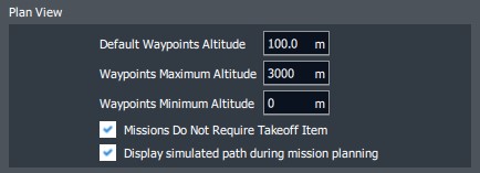
This value can be changed for each individual waypoint in the Mission tab. The default value can be set in the application settings of AMC when the Advanced Mode is enabled. Settings > General > Plan View
The vehicle has been designed to transition in the direction it was when positioned on the ground. This allows the operator to perform upwind transitions, regardless of the mission plan. During the transition phase, the vehicle may travel as much as 300 meters. The mission plan should account for this.
During the transition phase, the vehicle's heading may change due to wind influence. The mission plan should account for this.
The DeltaQuad EVO has been designed to fly autonomously, this is achieved by planning and executing missions. Missions are set through the Ground Control Station. They can be created and sent to the vehicle directly, loaded from an existing mission plan, or saved to a mission plan. This section covers the basics of planning a mission for the DeltaQuad EVO.
The operator can plan a takeoff and landing from the Fly View by selecting sectors that are free of obstacles at the approach altitude.
The DeltaQuad will take off and transition to aerodynamic mode into a set direction and orbit until new commands are given.
How to take off and land using Fly View will be discussed thoroughly in a later section of this manual.
In certain situations where launch and landing sites pose significant restrictions and obstacles, utilizing the Takeoff and Approach functionalities in Fly View becomes impractical. In such instances, it is advisable to employ the Plan View for comprehensive mission planning.
In the Plan View, you can create, edit and save missions, which can be uploaded to the DeltaQuad EVO. To plan a mission the DeltaQuad EVO does not need to be connected to Auterion Mission Control.
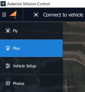
When opening Auterion Mission Control by default the Fly View will be selected. To change to the Plan View Click on the Menu icon in the upper left corner of the screen. A drop-down menu will open. Select the Plan tab.
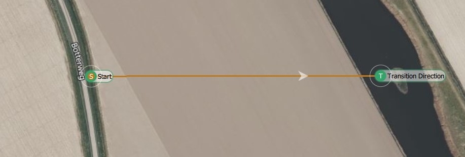
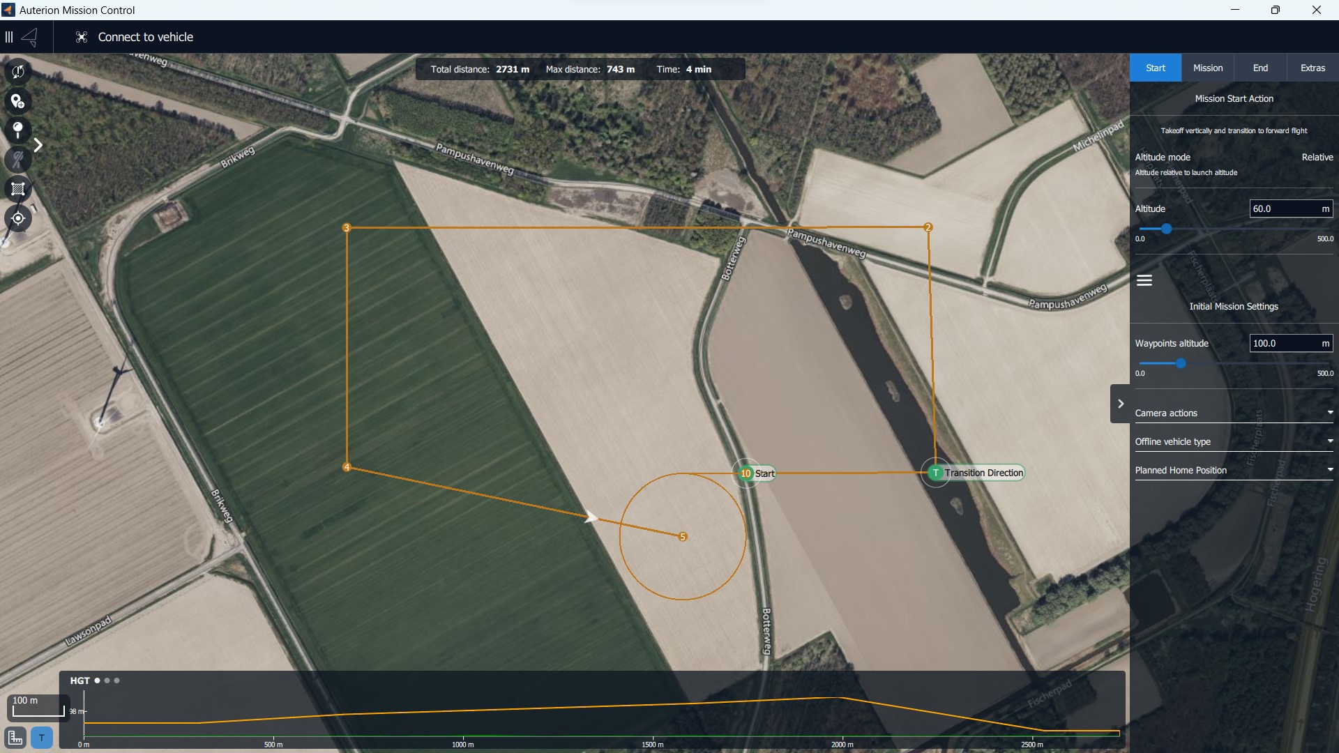
The image below shows a simple mission that starts with a Start and a Transition Direction item. The mission continues to fly through three waypoints which are followed by a Mission End Action.
The steps for creating missions are:
Change to Plan View.
Add commands to the mission and edit as needed.
Upload the mission to the vehicle.
Change to Fly View and fly your mission.
The following section describes all elements of the Plan View.
The Top menu bar consists of the same elements as the Fly View.
AMC Menu
Vehicle Status and Selector
Flight Mode
Emergency Actions and Arm Status
GPS Status
Radio Signal Strength
LTE Status and Signal Strength
Battery Status of the Vehicle
Battery Status of the Ground Control Station
Notifications Tab
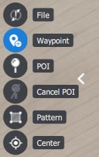
On the left side of the screen, the Plan Tools are located. The Plan Tools provide tools for working with plans, including adding waypoints, inserting survey patterns, saving, loading, uploading, and downloading plans. Some of the options are only displayed when working on a particular type of plan.
Only valid options are enabled (e.g. Download is grayed out if there is no mission on the vehicle).
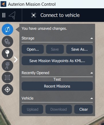
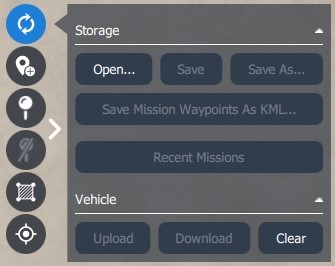
Storage
Open...
Open a plan file from storage, or clear the current mission in the Ground Control Station. The plan on the vehicle is not affected.
Save
Save previously opened or saved plans under the same name. AMC prompts to Save as if the file is new.
Save as...
Save the current plan under a new name.
Save Mission Waypoints as KML ...
Save the current mission as a KML file. KML files are used by Google Earth.
Recent Missions
Open a menu of recently created or loaded mission plans.
Upload
Upload the mission plan to the vehicle. Existing plans on the vehicle are cleared.
Download
Download the current plan from the vehicle. The current plan on the ground station is cleared.
Clear
Clear the mission plan on the vehicle and AMC. Disabled if no vehicle is connected.
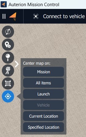
Mission
Center or zoom the map to include all mission waypoints.
All items
Center or zoom the map to include all plan items (missions, geofences, rally points)
Launch
Center the map at the point where the vehicle arms and takes off.
Vehicle
Center the map on the vehicle location. Disabled if no vehicle is connected.
Current Location
Center the map on the location of the Ground Control Station (AMC). Disabled if Ground Control Station does not have location or GPS.
Specified Location
Center the map on a specified location.
Enter geographic, UTM, or MGRS position information, to make it the new map center.
Under the top menu bar, the mission statistics are located.
The mission statistics give information about the total mission distance, the maximum telemetry distance, and the total mission time.
The Upload Button uploads the current mission, geofence, and rally points to the vehicle. The button has two states.
Upload Required
The mission plan has been changed since the last upload. A new upload is required.
Upload
The mission plan has not been changed and the vehicle has the latest version stored. It may be re-uploaded anyway.
At the top right of the screen, the Plan Item Selector is located.
The Plan Item Selector sets the part of the mission plan which is being edited.
The Plan Item Editors are displayed below the Plan Item Selector. Different item editors are displayed for each part of the mission plan:
Start: In this tab, you can edit the values of the Mission Start Action which consists of the Start or takeoff item and the Transition Direction item.
Missions: The mission tab shows a list of editors, one for each item in the mission (waypoint, commands, etc.)
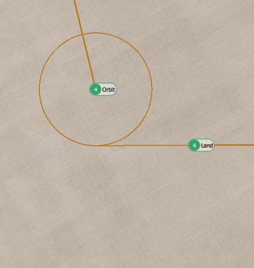
End: In this tab, you can edit the values of the Mission End Action. The Mission End Action can be either a landing pattern that consists of the Orbit and the Land item or only an Orbit item.
Extras: In this tab, you can add or remove GeoFence definitions, and select the current GeoFence region for editing on the map.
The distance between two points can be measured or the area in the form of a selectable polygon. Clear all will delete all Measurement Tools on the map.
Coordinates can be entered manually.
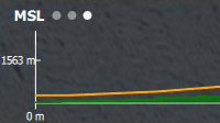
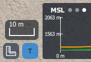
At the bottom of the screen, the Terrain Altitude Indicator is located.
A red line indicates a ground collision!
In the upper left corner of the Terrain Altitude Indicator, you can select between three different altitude measurements.
Simply tap the letters next to the three dots to change to the different altitude measurements:
HGT
Height above takeoff
MSL
Altitude above Mean Sea Level
AGL
Altitude above Ground Level
Above the Measurement Tool and the Toggle button, the Scale Marker is located.
It indicates the scale of the map depending on how much the map is zoomed in or zoomed out.
To use the zoom function the mouse wheel can be used or two fingers when operating on a touchscreen.
The DeltaQuad EVO will proceed to these waypoints, continuing in Aerodynamic mode.
To plan mission items such as regular waypoints select the Waypoint Tool from the Plan Tools on the left side of the screen.
Click anywhere on the map to designate a location for the waypoint.
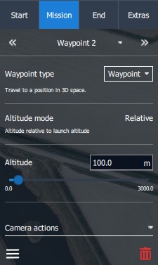
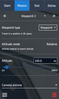
After placing the waypoint on the map, the Mission tab in the Plan Item Selector on the right side of the screen will open.
Choose and set up the desired mission item from the Waypoint type tab.
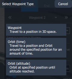
When AMC is used in Normal Mode three options are available.
The vehicle flies toward the location and altitude specified by the user. Once it arrives, it will proceed to the next mission item. If there are no further mission items following the Waypoint, the vehicle will orbit at the Waypoint's location.
The Altitude mode is the altitude above the launch elevation.
Set the altitude for the waypoint with the altitude slider.
The default range can be changed in the Application Settings. Settings>General>Plan View>Waypoints Maximum Altitude
When changing the altitude of a waypoint, the next waypoint's altitude is automatically set to that value.
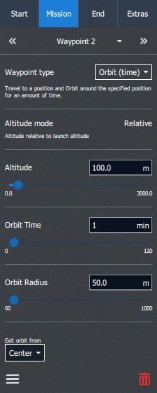
The vehicle flies toward the location and altitude specified by the user. Once it arrives, the vehicle will initiate an orbit and continue to circle that position. When the specified Orbit Time elapses, it will proceed to the next mission item.
The Altitude mode is the altitude above the launch elevation.
Set the altitude for the waypoint with the altitude slider.
Set the duration of how long the DeltaQuad EVO should orbit at the designated location.
Set the radius of the Orbit. We recommend a minimum radius of 100m. 75m is possible in calm winds.
Choose the vehicle's exit point from the Orbit.
At the bottom of the Mission tab, you can edit the position of the mission item, or delete it.
If the vehicle's altitude differs from the altitude of the next mission item, the vehicle will fly in a straight line toward that mission item.
The vehicle will not ascend or descend immediately to the altitude of the next mission item before reaching it.
If the vehicle can't reach the altitude of the next mission item due to an insufficient climb or descent rate, the vehicle will orbit at the location of the mission item to finish climbing or descending to the item's altitude.
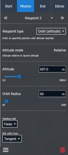
The vehicle flies toward the location at its current altitude. Once it arrives, the vehicle will initiate an orbit and start climbing or descending to the user-specified altitude. When the altitude is reached, the vehicle will continue to the next mission item.
The Altitude mode is the altitude above the launch elevation.
Set the altitude for the waypoint with the altitude slider.
Set the radius of the Orbit. We recommend a minimum radius of 100m. 75m is possible in calm winds.
Choose the vehicle's exit point from the Orbit.
At the bottom of the Mission tab, you can edit the position of the mission item, or delete it.
When using Orbit (altitude), the operator must be especially cautious about terrain collisions.
Orbit (altitude) is practical for reaching a desired altitude before the flight path continues or when the vehicle's climb or descent rate will not be sufficient to reach the required altitude en route.
A vertical takeoff or landing consumes significantly more energy than a fixed-wing flight. For maximum efficiency, an altitude between 25 and 35 meters is recommended for landing.
At every stage in the fixed wing portion of the flight, a vertical separation of at least 25 meters above the highest obstacle must be maintained.
When planning a landing either in mission, or quick-takeoff modes, the altitude must be set at least 25m above obstacles such as trees that may potentially fall in the flight path of the vehicle.
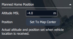
The altitude of the "Planned Home Position" defines the expected touch-down altitude.
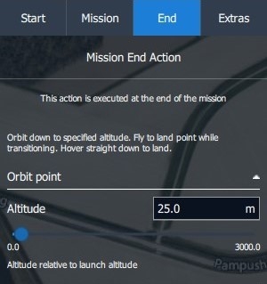
The back transition from fixed-wing flight (Aerodynamic mode) to multirotor flight (Hover mode) is performed at the altitude set in the "Orbit point" of the Mission End Action command.
Most wind forecasts are based on ground-level wind. Even 10 meters above the ground the wind can be significantly stronger.
During the transition phase of the "Transition Direction" item, the vehicle has limited navigational abilities and could drift from its intended direction. The transition should therefore always be performed at an altitude where it is safe for the vehicle to perform the transition in any direction.
The last action of the mission plan. Execute a landing pattern or loiter.
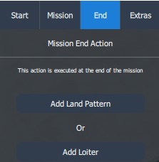
After the waypoints have been placed the Mission End Action has to be planned. When clicking on the End tab within the Plan Item Selector two options are available.
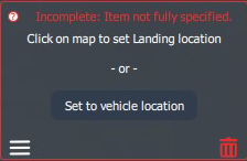
When selecting Add Land Pattern a window will appear with the request to choose a location on the map.
If the Ground Control Station is connected to the DeltaQuad EVO or the simulator you get a second option to set the Land item to the vehicle location.
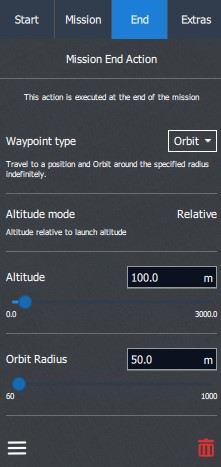
After the Land Pattern is positioned several options will be available in the Mission End Action tab on the right side of the screen.
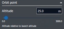
Altitude - The altitude at which the aircraft transitions from Aerodynamic mode to Hover mode prior to landing. The altitude is relative to the launch altitude.
At every stage in the fixed wing portion of the flight, a vertical separation of at least 25 meters above the highest obstacle must be maintained.
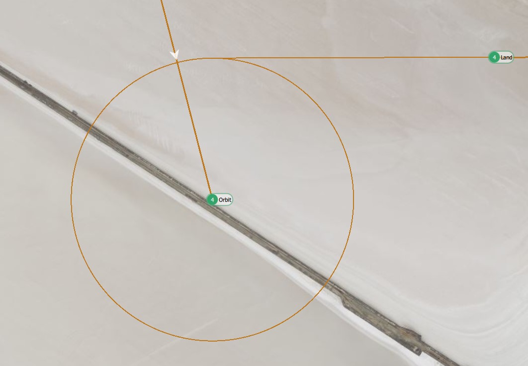
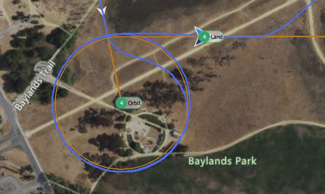
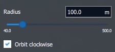
Radius - The radius of the descent circle. The aircraft will descend in Aerodynamic mode from the mission altitude to the specified altitude mentioned in the Altitude setting above.
The DeltaQuad EVO will orbit clockwise when the Orbit clockwise box is checked.
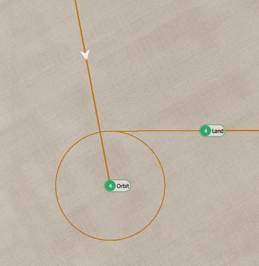
Disable that option to orbit counter-clockwise. This will change the location of the Orbit.
We recommend a minimum loiter radius of 100 meters. In strong winds, the loiter radius can be deformed and pushed by the wind. To mitigate this, we advise increasing the radius. For example, in stronger winds, set the radius to 150 meters or higher.
Heading - When placing the Land Pattern it automatically positions the Orbit and Land items in the same direction as the Start and Transition Direction items. As the DeltaQuad EVO needs to launch and transition into the wind it also needs to do the final approach and landing facing into the wind.
The heading can be changed by dragging the Land Pattern items on the map or using the Heading slider.
The DeltaQuad EVO needs to transition to Hover mode and land into the direction of the wind.
Altitude - The altitude of the Landing point is the relative altitude to the Start item where the vehicle is expected to touch down. When landing at the same altitude where the takeoff occurred this can be left at 0. The aircraft will confirm the setting by utilizing its integrated ground distance sensor.
Landing Dist - The distance between the Orbit and the Land item will be automatically set to 50m. You can change this distance by dragging the Land item on the map or by using the slider. Values between 50m and 200m are available.
At the bottom of the Mission tab, you can edit the position of the mission item, or delete it.
When choosing Add Loiter from the Mission End Action tab an Orbit waypoint will be placed on the map.
Weather conditions and mission within.
When installing Auterion Mission Control on a separate device such as a laptop or desktop pc, by default the Connection Manager will be available in the top bar of Auterion Mission Control.
Clicking the Flight Tools button in the lower-left corner of the screen will open an extra set of commands for controlling the vehicle. When the button is blue it is active and the extra set of commands will be visible. When the button is grey it is inactive and the extra commands will be hidden.
Depending on the payload a Point of Interest can be set. The camera will follow the specified location while the vehicle will remain on its flight path. The Point of Interest can be removed by clicking on Disable PIO .
When using the Set Altitude command the Altitude Slider will be presented with a fixed Minimum and Maximum Altitude. The operator can choose an altitude between these values.
Clicking the Map Tools button in the lower-left corner of the screen will open the Map Tools. When the button is blue it is active and the extra set of commands will be visible. When the button is grey it is inactive and the extra commands will be hidden.
The Marker Tool can be used to increase situational awareness. The set markers will be also displayed in the video feed.
The Measurement Tool button opens a menu.
Click on the map to specify the start location where the vehicle will initiate its takeoff. If the vehicle is currently connected, this location will automatically default to the vehicle's current position.
Adjust the Transition Direction icon displayed on the map. This action determines the transition direction for the vehicle, indicating how it will transition from Hover mode to Aerodynamic mode before proceeding to the next mission item. It is important to set the transition direction against the wind, ensuring that the vehicle is also facing the wind. The default distance between the Start item and the Transition Direction item is set to 70m and can be left at that value.
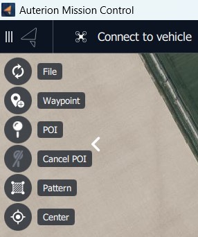
The File Tool provides options to create a new mission plan, load and save plans on the Ground Control Station, and upload, download, or clear the plan on the vehicle.
Select the Waypoint Tool to enable adding new waypoints to the map.
Select the Point Of Interest (POI) Tool to enable adding a point of interest on the map. The camera gimbal will point toward the last POI created.
Select the Cancel POI Tool to cancel the last point of interest on the map.
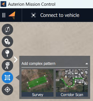
Select the Pattern Tool to add or load a survey or corridor pattern. Additionally, a KML/SHP file can be loaded.
The Center Tool gives multiple options to center the map on a mission, home, vehicle, all items, or a specified location.
In the lower-left corner, the Measurement Tool is located. When clicking on it a menu will show.
The Terrain Altitude Indicator is used to verify that the mission is set above ground level! It can be toggled visible or hidden using the button next to the Measurement Tool.
The designated location will be the position of the Land item . AMC will automatically plan an Orbit where the DeltaQuad EVO will descend to the set altitude, approach the Land item, transition to Hover Mode, and land at the designated location.
The Waypoint type and other settings can be adjusted as explained in the chapter
When the DeltaQuad EVO has completed operations it should be switched off, inspected, dismantled, and stored. Flight logs should be retrieved and registered.
Before approaching the vehicle to switch it off note the following;
The vehicle should never be approached when the motors are spinning.
In the unlikely event of a crash, the vehicle should not be approached within 15 minutes. The battery could have been damaged and may ignite.
Always stay clear of the propellers until the vehicle has been powered off by disconnecting the main flight battery.
To switch the vehicle off open the canopy and remove the lid. Then disconnect the main battery connector and remove the battery. The battery should be stored directly and safely.
After a landing, specifically a hard landing or a grass landing, the DeltaQuad EVO should be inspected for damage. Inspecting the vehicle visually at the landing site can help in determining the cause of any problems that might arise in the future. It is recommended, specifically when in doubt or with visible damage, to take pictures of the vehicle before dismantling it.
If there is any dirt on the vehicle or the propellers this should be removed with a damp cloth. Dirt on the wings, fuse, or propellers will significantly impact the performance.
Special care must be taken to inspect the propellers both before and after every flight. If there is any visible or palpable damage to a propeller it should be replaced directly in accordance with the preventative maintenance section.
Dismantle the vehicle in accordance with the assembly section. If you are able to transport and store the vehicle safely with only the wings detached this is recommended as it will reduce the risk of assembly problems.
The DeltaQuad EVO should be transported and stored inside the DeltaQuad EVO Flightcase.
When a sim card is installed inside the UAV, the logs will be uploaded automatically to your Auterion Suite account. Logs can also be manually retrieved through the Analysis section of the Ground Control Station.


