
Loading...
Loading...
Loading...
Loading...
Loading...
Loading...
Loading...
Loading...
Loading...
Loading...
Loading...
Loading...
Loading...
Loading...
Loading...
Loading...
Loading...
Loading...
Loading...
Loading...
Loading...
Loading...
Loading...
Loading...
Loading...
Loading...
Loading...
Loading...
Loading...
Loading...
Loading...
Loading...
Loading...
Loading...
Loading...
Loading...
Loading...
Loading...
Loading...
Loading...
Loading...
Loading...
Loading...
Loading...
Loading...
Loading...
Loading...
Loading...
Loading...
Loading...
Loading...
Loading...
Loading...
Loading...
Loading...
Loading...
DeltaQuad Evo Enterprise Edition eVTOL UAV is a limitation-breaking aerial solution for civilian and semi-government use.
Version number of this document: v2.0-27.06.2024
DeltaQuad Evo is a fixed-wing eVTOL UAV that has set new standards in the drone world. Longer flight times, extended transmission ranges, and increased payload flexibility are all available in Evo Enterprise Edition. Its advanced features make it ideal for mapping and surveillance missions like infrastructure inspection, precision agriculture, safety monitoring, or light cargo transportation.
Evo Enterprise edition is designed for civilian and semi-government use. It operates based on the DeltaQuad Controller on the world-wide license free 2.4Ghz band and offers radio options up to 30 km range.
This section describes how to create an Auterion Suite account.
In order to use Auterion Suite you need to create an account. Ignore the following steps if you already have an Auterion Suite account.
Please follow this link: https://suite.auterion.com/login
Click on Register for an Auterion account.
Follow the given instructions and fill in all necessary information.
Accept the Terms of Service and Privacy Policy by checking the box. Continue by clicking on Create Organization.
Please check your email for an invitation.
Follow the link by clicking on Create account.
Add a name and click on Next.
Choose a password and click on Activate Account.
Log into your account.
You created successfully your Auterion Suite account.
For further documentation about Auterion Suite please follow this link .
The following section describes how to activate your DeltaQuad Evo.
Activating your vehicle will connect it to Auterion Suite. This will allow you to access cloud features and manage your vehicle remotely.
To activate a vehicle:
Make sure the Evo is powered off.
Connect your vehicle to your computer via USB-C.
Power your vehicle.
Open a browser on your computer and navigate to the vehicle's WebUI:
To activate a vehicle make sure your vehicle is connected to the Internet using Auterion Mission Control > Connectivity tab.
Click on Activate now or Scan the QR code.
You will be directed to Auterion Suite, where you'll see this pop-up window to activate your Skynode.
Click on Activate and your vehicle will be visible under Fleet Management > Vehicles.
Select a vehicle from the All Vehicles list.
Click on Rename vehicle in the top bar.
Enter the new vehicle name and click on Rename Vehicle.
A vehicle is a collection of parts. An airframe, a Skynode, a flight controller, and more. These various pieces of the vehicle make up the complete "vehicle identity."
To view the serial numbers and IDs of the components associated with a given vehicle, click the "fingerprint" button near the vehicle's name on the Vehicle Page.
This will open up a window that shows all of the IDs of the components that make up the vehicle in the Suite. Each ID controls a specific component. For example, the flight controller ID is how the logs coming out of a flight controller as associated with the vehicle page in the Suite.
In this section, we cover the steps for assembling and disassembling the DeltaQuad Evo.


The vehicle may not be operated or flown near or over people, roads, vehicles, buildings, or anything that could result in damage or danger to people or property.
Radio or video transmitters might require special licensing and/or permits.
DeltaQuad or its affiliates can not be held responsible for vehicles that have not been operated or maintained in accordance with the guidelines set forth in this manual, or for behavior resulting from changes made to the vehicle.
This operations manual is provided "As-Is". No rights can be obtained from the contents of this manual.
The original language of this document is English, if this document is read in a translation to any other language, the interpretation of the English version takes precedence.
Software used in conjunction with the vehicle is provided under their respective license and warranty.
The vehicle is provided in accordance with the DeltaQuad Warranty and under the DeltaQuad Terms & Conditions.
The DeltaQuad Evo is not a toy and is not suitable for people under the age of 16.


Take the DeltaQuad Evo out of the flight case and place it on a flat surface with the landing gear deployed.
The wing has a big spar close to the leading edge and a smaller spar close to the trailing edge. In front of the big spar is a keying mechanism located in the form of a cuboid.
This keying mechanism prevents mounting the wings on the wrong side.
The wings of the DeltaQuad Evo must be mounted in such a way that the wingtips point downwards.
Slide the carbon spars of the wings into the corresponding blind holes of the fuselage.
When fully locked a clicking sound from the wing lock mechanism must be audible and the wing lock must sit flush with the fuselage.
The wing is not properly installed if the wing lock doesn't make a click sound or doesn't sit flush with the fuselage.
To disassemble the DeltaQuad Evo, follow the steps for the assembly in reverse order.
Press down the wing lock mechanism with the thumb while the same hand is holding the fuselage in place. With the other hand pull the wing away from the fuselage.
When storing the fuselage inside the flight case, the landing gear must be deployed.
It is recommended to transport the DeltaQuad Evo in the flight case.
The DeltaQuad Evo and its accessories are stored in a rugged flight case.
1 x Fuselage
2 x Wing
4 x DeltaQuad Evo Semi Solid-State Li-ion battery
DeltaQuad Dual Battery Charger
1x auxiliary battery payload box
1x empty payload box
Ground Control Station (Controller or ruggedized laptop) and accessories
Optional payloads
When removing the fuselage from the flight case you gain access to five extra compartments
*Depending on the Evo version, the Ground Control Station can be either a hand controller or a ruggedized laptop. The functionality and use of this equipment will be discussed in a later chapter of this manual.
The following section describes what Auterion Suite is and how to use its services.
Auterion Suite refers to a software platform developed by Auterion.
With every mission, data is automatically transferred into the cloud-based Auterion Suite to provide real-time information captured by the robot while it’s still operating, without any manual intervention.
All flight logs are automatically uploaded for every vehicle and every pilot, and log data are analyzed and available to download as compliance reports.
Auterion Suite enables holistic and scalable fleet management by providing updated information on the vehicle health status, predictive maintenance actions and over-the-air software updates.
Real-time data for quick decision-making
The UAVs can send operational data and live video automatically to the Suite, while they are still in the air, without even pushing a button.
Data and automated workflows
Enable end-to-end automated workflow, from the vehicle operating, over the air to the cloud, and into third-party applications to process the captured data.
Holistic and scalable fleet management
Manage your complete fleet of drones, assets, operators and missions.
Analysis and predictive maintenance
The platform handles software updates, tracks every vehicle for predictive maintenance, and monitors components to flag when you need a replacement.
The DeltaQuad Evo comes with 5 propellers, 1 composite "pusher" propeller, and 4 carbon fiber VTOL propellers. The propellers should already be attached when you receive the vehicle. When replacing the propellers please follow these guidelines.
The VTOL propellers consist of 2 Clock Wise (CW) propellers and 2 Counter Clock Wise (CCW).
The bullet-type nut on the propeller adapters is self-tightening, which means they close by turning them in the opposite direction of how the motor/propeller spins. This is done to ensure the propellers do not become detached when the motor spins up. This means that to undo the nut on motors 1 and 2 it turns left, and on motors 3 and 4, it turns right.
The propellers are centered with a small ring inside the mounting hole, this should result in the propeller sitting tightly around the shaft.

Mount the propellers in the following positions noting the direction of the propeller as indicated below:
The propellers are attached by removing the motor nut and washer, sliding the propeller on the shaft, sliding the washer on top of the propeller, and fastening the nut.
For the vertical motors (VTOL motors), please make sure to install the washer in the right orientation. The washer has a wider side on top.
After changing the pusher propeller a test flight is necessary to verify that the vibration of the pusher motor is within tolerances. Please contact our support ([email protected]) and share the log file for review.
The DeltaQuad Evo pusher propeller is an APC 15x10E propeller that contains a modified ring to mount properly on the DeltaQuad Evo pusher motor. Please only use DeltaQuad-approved and balanced pusher propellers.
The pusher propeller should be mounted so that the propeller produces thrust towards the rear, this means that the top of the propeller (the side that has the text engraved) should face the motor as shown in the diagram below.
Note: All propellers are balanced in our factory by hand. This can leave scratch marks on the propeller blades. This does not indicate damage or that the propellers are used. A sign of damage can be structural weakness such as a bent propeller blade. If you find gouges or missing parts anywhere at the tip, the outboard region, or the trailing edge of the blade you need to replace the propeller.
1
Controller* and accessories
2
Battery compartment
3
Payload compartment
4
Dual Charger compartment
5
Ruggedized laptop*


Before the mission plan can be created, the following steps should be taken to ensure safe execution:
A mission plan should only be executed after a thorough inspection of the entire mission on site. All altitude differences and obstacles should be known and taken into account.
Missions must be allowed to be executed in accordance with local laws and regulations.
The mission path must be free of obstructions for at least 200 meters in each horizontal direction.
During fixed-wing flight (Aerodynamic mode) the vehicle should stay 50m above ground level, near the end of the mission, to reduce landing energy consumed, an altitude of 25m above ground is recommended.
For maximum endurance a takeoff altitude can be set to 25m, however, to ensure the safety systems can function properly, the takeoff altitude should be at a minimum of 60 meters above ground level.
The takeoff and land sites must consist of a level, flat surface that is free of obstructions for at least 5x5 meters.
The takeoff altitude should be set high enough for the vehicle to be able to perform a transition in any direction.
The weather conditions must fall within the maximum allowed conditions.
Both the front and back transition paths must be planned in such a way that the vehicle is pointing with its nose toward the wind while performing the transition.
The intended mission should not consume more than 85% of the total energy available.
At any point in the mission, the vehicle must be able to return to its takeoff point in a straight line at its current altitude.
At any point in the mission, the vehicle must be able to initiate an unscheduled landing without causing damage to itself or its environment.
This chapter explains the process for firmware and software updates.
When purchasing a DeltaQuad Evo, operators will be notified via email of relevant firmware updates for your vehicle and software updates for the Ground Control Station (GCS).
The email notification contains a download link for the required firmware and software, instructions on how to perform the update, and a method to verify successful completion.
To keep the DeltaQuad Evo warranty intact, the firmware update must be performed within two weeks of receiving the email notification.
There are two different updates available.
In this update, the firmware of the DeltaQuad Evo flight controller needs to be updated.
In this update, your DeltaQuad Evo Ground Control Station requires a software update.
If you have questions after receiving the update instructions, please contact our support at [email protected].


This chapter explains how to connect to the DeltaQuad Evo simulator in Auterion Suite.
The DeltaQuad Evo simulator can be used to get familiar with the Auterion Mission Control interface and to use the pilot controls before actually flying the Evo for the first time.
Requirements:
A registered Auterion Suite account.
A computer running either Linux, Windows 10/11, macOS, or any Android device.
An installation of AMC.
A stable internet connection.
The simulator has some limitations to be aware of:
The simulator does not accurately simulate battery usage.
The simulator uses always a wind direction coming from the east. Therefore all the missions flown in the simulator will take off and transition in that direction.
To use the DeltaQuad Evo simulator, please follow the instructions:
Go to the Downloads tab on the left side of the screen. Click on Additional Releases.
Click on Download 1.22.3 and select the operating system of your choice. The download will start.
Follow the instructions to install AMC.
In Auterion Suite, click on the Simulations tab on the left side of the screen. Click on Start Simulation.
Choose a name for the simulation, and DeltaQuad Evo (VTOL) as the vehicle.
Choose one of the three available locations.
Set the Simulation Run Time.
For full functionality, we recommend selecting Software Version 2.5.1.
Click on Creating simulation.
As the simulation is cloud-based, the process of creating one may take several minutes.
After the simulation is created, copy the given IP address to the clipboard and remember the Port, which is always 5790 for the simulator.
On the secondary device, open AMC. Navigate to AMC menu > Comm Links. Click on Add at the bottom of the Screen.
Enter a Name of your choice and choose Type: TCP.
Copy the IP address of the simulation into the field of the Host Address, and add 5790 as the TCP Port. Click OK.
Choose the comm link you created and click on Connect.
A connection with the simulator should be established within seconds.
More information about the simulator can be found .
To calculate the expected performance of the DeltaQuad Evo based on specific payloads and conditions, please refer to the DeltaQuad Evo Performance Calculator.
Dimensions:
Wingspan
269 cm
All flight characteristics are based on optimized settings at sea level
These values assume 90% battery usage, and low wind conditions and include a low-altitude vertical takeoff and landing at sea level.
* The tolerances are provisional and subject to change
In this chapter, we will discuss the DeltaQuad Semi Solid-State Li-ion battery, how to handle it, how to place it inside the DeltaQuad Evo, and how to power up the vehicle.
In this section, we will discuss how to bind the DeltaQuad Controller with the DeltaQuad Evo air unit.
After a factory reset has been performed on the DeltaQuad Controller, it might be necessary to rebind the controller with the air unit located in the DeltaQuad Evo. Please follow the steps below.
Power on the DeltaQuad Evo and the DeltaQuad Controller. Open Auterion Mission Control. In the upper right corner of the screen, the Radio icon is located. If it has a strike-through and the radio link is not available, a rebinding is required.
Remove the hatch of the avionics bay by loosening the two screws with a Torx tool (T10).
Please use a medium-strength lock bond when tightening the screws again.
In the avionics bay you will see the radio modem. Push the SET button. This puts the modem into the bind mode. When in bind mode, the LED of the modem rotates through different colors.
On the Controller, open the Radio Settings app.
Open WIRELESS PARAMETER CONFIGURATION.
Tap on FREQUENCY MATCHING.
Click on Confirm.
After the binding process has been successful, a connection will be established between the DeltaQuad Evo and the DeltaQuad Controller.
The DeltaQuad EVO has been designed to fly autonomously, this is achieved by planning and executing missions. Missions are set through the Ground Control Station. They can be created and sent to the vehicle directly, loaded from an existing mission plan, or saved to a mission plan. This section covers the basics of planning a mission for the DeltaQuad EVO.
The operator can plan a takeoff and landing from the Fly View by selecting sectors that are free of obstacles at the approach altitude.
The DeltaQuad will take off and transition to aerodynamic mode into a set direction and orbit until new commands are given.
How to take off and land using Fly View will be discussed thoroughly in a later section of this manual.
When operating in high-temperature environments, special attention must be given to the cooling and storage conditions of the DeltaQuad Evo:
Airflow Requirement: If the ambient temperature exceeds 25°C for more than 5 minutes, the DeltaQuad Evo must be placed in an environment with at least 2 m/s airflow to prevent overheating of internal components.
This section explains the functionality of the Payload Manager.
The Payload Manager provides an overview of the installed payloads and allows you to edit their settings. It also displays the offset of the main battery in the nose of the vehicle, with the option to adjust the value. Additionally, you can enable or disable the white navigation lights on the Evo's wing tips.
Power up the vehicle and the GCS.
Open the WebUI: after a connection between the Evo and the GCS has been established.
Field-proven stabilized cameras for commercial, industrial, and security applications.
This section will discuss how to install, set up, and use all NextVision payloads.
This section will describe in detail the functionality of every available payload for the DeltaQuad EVO.
Direct Sunlight Exposure: The aircraft must not be exposed to direct sunlight for more than 5 minutes while idle. Prolonged exposure can cause excessive heating of internal systems. It is best practice to provide shade for the aircraft during pre-flight preparations. During flight, the Evo benefits from sufficient natural airflow to maintain stable operating temperatures, even in direct sunlight.
Storage Conditions: Always store the Evo in a stable ambient temperature environment. Avoid moving the aircraft directly from cold to warm conditions, as this may lead to moisture condensation inside sensitive electronics.
Operations during rain are generally not recommended.
Tolerance: The DeltaQuad Evo is designed to tolerate moderate rain (up to 7 mm/h) while in flight. However, the aircraft must not be launched during active rainfall.
Airspeed Sensor Considerations: Exposure to rain during flight may result in airspeed sensor failure. In such cases, the onboard control system automatically switches to fixed-thrust flight mode, allowing the mission to continue safely. This mode increases power consumption and reduces maneuverability.
Post-Flight Procedure After Rain: If the airspeed sensor is affected by moisture or has failed due to rain, the aircraft may not be relaunched within 24 hours of the incident. Before the next takeoff, the airspeed sensor must be verified to function correctly.
Payload Considerations: ISR payloads may experience reduced visibility or performance degradation when exposed to rainfall.
Operation in cold conditions requires additional caution to prevent icing and control-surface obstruction.
Temperature Range Restriction: The DeltaQuad Evo must not be flown between −5°C and +5°C in the presence of any atmospheric moisture (e.g., fog, drizzle, or light rain). Moisture in this temperature range can freeze instantly on the wings, fuselage, or propellers, leading to loss of lift and thrust.
The DeltaQuad Evo must not be flown in fog, and flight through cloud layers should be minimized. These conditions can lead to unstable flight behavior due to turbulence and may cause moisture accumulation or ice formation on control surfaces.
Takeoff and Landing: The DeltaQuad Evo must not take off directly from snow or wet mud, as these materials can adhere to the landing gear. Once retracted, they may solidify or freeze, potentially preventing proper gear deployment during landing.
Post-Landing Procedure: After operating in snowy or muddy environments, the landing gear must be thoroughly cleaned before subsequent missions.
Clean the fuselage and wings, this will improve performance.
Inspect the avionics, and make sure all components are still securely attached in their proper place and all connectors are securely fastened.
To keep your vehicle in the best condition and safe to operate beyond this point scheduled maintenance should be performed. A maintenance kit can be ordered from your DeltaQuad representative.
The DeltaQuad EVO has been designed to allow easy replacement of components. Every component on the DeltaQuad EVO is available as a replacement part.
The maintenance kit includes detailed instructions on all replacement parts.
The simulator is limited to three locations to choose from.
The available ISR payload is limited in its functionality.
The simulator runs best with AMC v.1.22.3 available via the Downloads tab in Auterion Suite.


In certain situations where launch and landing sites pose significant restrictions and obstacles, utilizing the Takeoff and Approach functionalities in Fly View becomes impractical. In such instances, it is advisable to employ the Plan View for comprehensive mission planning.


The Payload Manager can be used to verify whether all payloads are registered by the system. Payloads integrated by DeltaQuad are preconfigured and require no additional changes. For Custom Payload Kits, relevant values can be added in the Payload Manager for the respective payload. The nose battery offset is set during production and only needs to be adjusted if hardware in the avionics bay is changed.


Length
75 cm
Height
33 cm (landing gear extended)
Wing area
84 sq. dm.
Payload bay
20 x 20 x 11 cm
Flightcase dimensions
112 x 82 x 46 cm
Flightcase weight
~ 30.4 kg
Weight and Payload:
Empty weight
4.8 kg
Empty weight including 1 battery
6.8 kg
Maximum takeoff weight
10 kg
Payload capacity
3 kg
Flight Characteristics with Dual battery:
Flight speed
16.54 m/s (60 km/h)
Payload capacity
1 kg
Maximum flight time
272 minutes (4 hours 32 minutes)
Range through air
270 km (168 mi)
Power
Battery type
Semi Solid State Lithium-ion
Battery cells
6
Battery capacity
22Ah per battery
Tolerances *
Maximum takeoff/landing wind
12.5 m/s (45 Km/h)
Maximum wind cruise flight
14 m/s (50 Km/h)
Maximum precipitation
7mm/h (Drizzle)
Operating temperature
Between -20 and +45 Celsius
Maximum flight altitude AMSL
13.000ft (4000m)


When the DeltaQuad EVO has completed operations it should be switched off, inspected, dismantled, and stored. Flight logs should be retrieved and registered.
Before approaching the vehicle to switch it off note the following;
The vehicle should never be approached when the motors are spinning.
In the unlikely event of a crash, the vehicle should not be approached within 15 minutes. The battery could have been damaged and may ignite.
Always stay clear of the propellers until the vehicle has been powered off by disconnecting the main flight battery.
To switch the vehicle off open the canopy and remove the lid. Then disconnect the main battery connector and remove the battery. The battery should be stored directly and safely.
After a landing, specifically a hard landing or a grass landing, the DeltaQuad EVO should be inspected for damage. Inspecting the vehicle visually at the landing site can help in determining the cause of any problems that might arise in the future. It is recommended, specifically when in doubt or with visible damage, to take pictures of the vehicle before dismantling it.
If there is any dirt on the vehicle or the propellers this should be removed with a damp cloth. Dirt on the wings, fuse, or propellers will significantly impact the performance.
Special care must be taken to inspect the propellers both before and after every flight. If there is any visible or palpable damage to a propeller it should be replaced directly in accordance with the preventative maintenance section.
Dismantle the vehicle in accordance with the assembly section. If you are able to transport and store the vehicle safely with only the wings detached this is recommended as it will reduce the risk of assembly problems.
The DeltaQuad EVO should be transported and stored inside the DeltaQuad EVO Flightcase.
When a sim card is installed inside the UAV, the logs will be uploaded automatically to your Auterion Suite account. Logs can also be manually retrieved through the Analysis section of the Ground Control Station.
Never charge batteries unattended unless you charge inside a Battery Safe. When charging Li-ion batteries you should always remain in constant observation to monitor the charging process and react to potential problems that may occur.
If at any time you witness a battery starting to balloon or swell up, discontinue the charging process immediately. Disconnect the battery and dispose of it safely. Continuing to charge a battery that has begun to swell will result in fire. Likewise, never use a battery if you find it swollen or ballooned.
Since a delayed chemical reaction can occur, it is best to observe the battery as a safety precaution. Battery observation should occur in a safe area outside of any building or vehicle and away from any combustible material.
Wire lead shorts can cause a fire! If you accidentally short the wires, the battery must be placed in a safe area for observation for approximately 1 hour. Additionally, if a short occurs and contact is made with metal (such as rings on your hand), severe injuries may occur due to the conductibility of electric current.
A battery can still ignite even after 1 hour.
A battery that makes a hissing sound is almost certain to ignite. Consider your own safety and that of your environment before attempting any action
In the event of a crash, after a 15-minute period to ensure the battery was not compromised, you must remove the battery and dispose of it safely.
Only place the battery before the flight, and remove the battery directly after the flight. Always transport the battery in the dedicated compartment of the flight case or in a safe transportation unit such as a fireproof bag or storage container.

This chapter gives an overview of the single and dual Custom Payload Kits.
The DeltaQuad Custom Payload system is a versatile and modular solution designed for users who need to integrate custom payloads into the DeltaQuad Evo platform. It offers customizable development kits that include everything required to design, build, and attach payloads to the drone. With available 3D models, users can modify the mounting structure to ensure tool-less integration, making the payload attachment quick and efficient.
Product Variants:
Single Payload: This option provides a compact payload space with dimensions of 225.6 x 103 x 107.5 mm.
Dual Payload: Larger, with two configuration options depending on the number of interface boards (IO), the dual payload provides additional room for custom devices with a size of 225.6 x 207 x 107.5 mm.
Customization Features: Users can further customize the payload plate using the provided CAD files, allowing specific designs to accommodate custom equipment. The provided plates come pre-fitted with mounting holes, making modifications easier.
The following PDF contains all the necessary information for integrating custom payloads into your DeltaQuad Evo. Click to download.
The following section describes the components of the maintenance kit, their installation, and the benefits of using them for optimal performance.
Scheduled Replacement of DeltaQuad Evo Maintenance Kit Components
To maintain the peak performance and reliability of your DeltaQuad Evo, it is crucial to adhere to scheduled maintenance practices, including the replacement of the components from the maintenance kit. Due to the nature of their design and usage, components such as VTOL arms, the pusher motor pod, the wingtips, and propellers incorporate moving parts and utilize lubricants for optimal function.
After approximately 12 months, these components may experience wear and tear, and the lubricants used within them can begin to dry out. This can affect the overall performance and lifespan of the drone if not addressed proactively. Therefore, it is recommended to replace these components with new ones provided in a DeltaQuad Evo maintenance kit.
By replacing these parts at the recommended interval, you ensure that your drone continues to operate at its best, maintaining flight stability, efficiency, and longevity. This proactive approach to maintenance helps mitigate potential issues before they impact your drone's performance during missions.
The DeltaQuad Evo maintenance kit includes the following components:
VTOL Arms
The kit includes four VTOL arms:
Two VTOL arms with clockwise rotating motors and propellers
Two VTOL arms with counter-clockwise rotating motors and propellers
These VTOL arms come pre-assembled with landing gear, ESC (Electronic Speed Controller), motors, and propellers balanced by DeltaQuad to achieve the lowest vibration profile, ensuring smooth and stable flight performance.
Pusher Motor Pod
A fully assembled pusher motor pod is included in the kit. This pod comes with:
A housing for the ESC, motor, and propeller
Pre-installed and balanced for optimal thrust and minimal vibration, the pusher motor pod provides the forward propulsion necessary for fixed-wing flight. It complements the VTOL arms' vertical lift, aiding during both ascent and descent by holding the vehicle's position.
Wingtips
The maintenance kit also contains a pair of interchangeable wingtips. Each wingtip includes:
One servo for precise control of the drone's elevon
One LED for enhanced visibility and status indication
The wingtips are designed to be easily attachable and interchangeable, allowing for quick replacements or repairs. Either wingtip fits on both sides of the drone.
Pre-installed and Balanced Propellers
It is important not to remove the installed propellers, as this would negate their pre-installed and balanced state, designed to achieve the lowest vibration profile.
All propellers in the kit are pre-installed on their respective motors and balanced by DeltaQuad. This balancing process minimizes vibration, crucial for maintaining flight stability and extending the lifespan of both the motors and the drone's structural components.
The following section describes how to do a factory reset on the DeltaQuad Evo Controller.
If the DeltaQuad Controller is experiencing issues such as app malfunctioning, crashes, or general malfunctioning, performing a factory reset can often resolve these issues.
Follow the steps below to reset your controller to its factory settings:
Power on the controller.
Go to the Settings.
Go to System.
Navigate to Reset options.
Choose Erase all data (factory reset).
This process might take a few minutes. After the factory reset, make sure that the controller and all apps work properly. If problems should persist, please contact [email protected].
RGB AND THERMAL - Single payload
The Raptor is a lightweight long-range dual EO-IR stabilized camera turret. It features a significant IR range increase and a X80 EO zoom.
ZOOM
X80 (X40 + X2 digital)
FOV
60° WFOV – 1.5° NFOV – 0.75° DFOV
THERMAL RESOLUTION
1280×720
PITCH FOR
Takeoff in Hover mode and transition to Aerodynamic mode.
Before creating a new mission plan make sure that there are no items such as waypoint commands on the map.
First, enter the Plan view by selecting the Plan tab from the AMC menu.
You can clear all waypoints from AMC and the vehicle by selecting the File Tool from the Plan Tools. Choose the clear option.
The DeltaQuad EVO requires a compass calibration in the following conditions:
When indicated by events described in this manual.
When the telemetry readings are inconsistent with reality.
The DeltaQuad EVO requires a gyro calibration in the following conditions:
The DeltaQuad EVO records onboard logs that contain vast amounts of information regarding the flights. These onboard logs will be uploaded to Auterion Suite through Cloud connectivity.
Asset management
Keep track of payloads, parts, and other peripherals, see asset usage per flight, lifecycle state, and proactive measures.
A vertical takeoff or landing consumes significantly more energy than a fixed-wing flight. For maximum efficiency, an altitude between 25 and 35 meters is recommended for landing.
At every stage in the fixed wing portion of the flight, a vertical separation of at least 25 meters above the highest obstacle must be maintained.
When indicated by the UAV
The DeltaQuad EVO requires an accelerometer calibration in the following conditions:
When indicated by the UAV
The DeltaQuad EVO requires a level horizon in the following conditions:
When indicated by the supplier
Sensor calibration is performed in Auterion Mission Control. To access the sensor calibration, you will need to switch the vehicle on and establish a connection between the Ground Control Station and the vehicle. Navigate to the settings view and select the Sensors tab.
QGroundControl will issue a warning about sensor calibration over a WiFi connection. This can safely be ignored by clicking OK.
The following sensor calibrations should be performed:
Compass
Gyroscope
Accelerometer
Level Horizon
All calibrations should be performed with the VTOL modules attached, and any additional payload installed and powered on.
After every calibration step, the autopilot must reboot. The autopilot can be rebooted quickly from the parameters tab under the tools button.
A compass calibration is best performed outside, away from metallic objects, electrical or magnetic interference. To start the compass calibration, click the compass button and follow the instructions on the screen. The calibration process starts when clicking OK. The autopilot orientation parameter in the GCS should remain unchanged. A compass calibration involves rotating the vehicle 3 times over all axis. This calibration step can be performed by hand. The canopy should be closed and the LiPo battery and any additional payload should be inserted and securely fastened.
Perform the calibration as indicated by the images on the ground station. When all axis are finished (images turn green) click OK, leaving the external magnetometer orientation unchanged. Then reboot the vehicle.
After the compass calibration ALWAYS verify the compass is reading correctly by pointing the vehicle north, east, south and west and at every turn verify that the vehicle icon on the ground station is pointing in the correct direction, and remains pointed in that direction for at least 30 seconds. if the compass is not reading correctly by more than 8 degrees, please retry the calibration. If the problem persists please contact Vertical Technologies.
The gyroscope calibration is best performed indoors. It requires the vehicle to sit level based on the VTOL arms. To level the vehicle based on the VTOL arms it is recommended to find a level surface (a table) and place 4 objects of equal height under the quadcopter motors. For example soda cans. The foam underside of the vehicle should be free from the table and the carbon VTOL arms should sit level horizontally.
When the vehicle is sitting level, press OK to start the calibration. This will complete in about 20 seconds. The vehicle should not be touched or moved during the calibration process. Then reboot the vehicle. If, for any reason, the vehicle is moved during the calibration process then repeat the process from the beginning.
To start the accelerometer calibration, click the accelerometer button and follow the instructions on the screen. The calibration process starts when clicking OK. The autopilot orientation parameter in the GCS should remain unchanged. An accelerometer calibration involves positioning the vehicle on all axis. This calibration step can be performed by hand. The canopy should be closed and the LiPo battery should be inserted and securely fastened.
Perform the calibration as indicated by the images on the Ground Control Station, ensuring the vehicle is motionless at each point in the calibration process. Then reboot the vehicle.
WARNING: This calibration is rarely needed outside of the factory. Performing this calibration incorrectly can cause the vehicle to become unstable or crash. Do NOT perform this calibration without consulting your DeltaQuad representative.
Before leveling the horizon all other calibrations, except compass calibration, must have been completed.
The Level Horizon calibration is best performed indoors. It requires the vehicle to sit level on a calibrated flat surface with the landing gear retracted.
When the vehicle is sitting level, press OK to start the calibration.


-45° to +80°
YAW/ROLL FOR
-180° to +180° Optional 360° Continuous
WEIGHT
850 grams
DIMENSIONS
D-90mm x H-120mm

Find a flat surface like a table big enough to fit the DeltaQuad Evo's fuselage.
Take the fuselage of the DeltaQuad Evo out of the flight case.
Remove the hatch, as this gives more stability when the fuselage is lying upside down on the table.
Put the fuselage upside down on the table.
To remove the VTOL arm, two screws need to be loosened. To access the screw heads, the landing gear leg must be fully deployed. If the landing gear is retracted, it can be gently deployed manually.
Use a size 2 hex key to loosen the two long screws located under the landing gear leg when it is retracted.
After removing the two screws, the VTOL arm can be detached. Hold the opposite VTOL arm with one hand for stabilization and pull the lower VTOL arm towards you in a straight line. Avoid wiggling from side to side or up and down.
The maintenance kit comes with four VTOL arms: two with clockwise (CW) propeller rotation and two with counter-clockwise (CCW) propeller rotation. Each VTOL arm has an inscription inside its hollow end. The inscription inside the VTOL arm must match the inscription on the respective T-section mount that holds the VTOL arm to the fuselage.
Hold the opposite VTOL arm with one hand for stabilization.
The T-section mount has an alignment groove for the VTOL arm on each side.
Align the VTOL arm so that it catches the alignment groove, then push it forward in a straight line. Avoid wiggling from side to side or up and down.
Push until the VTOL arm is fully aligned and set.
Apply a small amount of threadlocker to the tip of the screw.
Insert and tighten the first screw with moderate force until it is firmly in place. Avoid using excessive force to prevent overtightening and potential damage.
Repeat step 9. and 10. for the second screw.
The VTOL arm is now installed. Ensure that it is securely aligned and properly set in place. Double-check that both screws are snug but not overtightened to avoid any damage. Repeat the process for the remaining VTOL arms if necessary.
If you should encounter problems during the installation process please contact [email protected] for further assistance.

When selecting the Start tab the option Add VTOL Takeoff is available.
Click on the map to specify the start location where the vehicle will initiate its takeoff. If the vehicle is currently connected, this location will automatically default to the vehicle's current position.
Adjust the Transition Direction icon displayed on the map. This action determines the transition direction for the vehicle, indicating how it will transition from Hover mode to Aerodynamic mode before proceeding to the next mission item. It is important to set the transition direction against the wind, ensuring that the vehicle is also facing the wind. The default distance between the Start item and the Transition Direction item is set to 70m and can be left at that value.
Set the VTOL Takeoff altitude in the Plan Item Editor. This is the altitude at which the vehicle transitions from Hover mode to Aerodynamic mode.
We recommend a minimum VTOL Takeoff altitude of 60m for all safety features to function properly. Always make sure to set an altitude that surpasses the height of all obstacles present between the Start and Transition Direction waypoints.
Please be aware that the altitudes of mission items in the Plan View are relative to the launch altitude, rather than Above Ground Level (AGL).
For maximum endurance, this value can be set as low as 25m. At that altitude, the safety features might not function properly in the event of an emergency.
In Hover mode, the DeltaQuad EVO uses up to 12 times more energy compared to the Aerodynamic mode (Fixed-wing mode). We recommend setting the VTOL Takeoff altitude not higher than 100m as this will have an impact on the total flight time. As a rule of thumb, every additional minute ascending in Hover mode will take off 10km from the total mission length. Every extra minute of descending in Hover mode will take off 7km of the total mission length.
In the Initial Mission Settings, the default Waypoints altitude can be set.
This value can be changed for each individual waypoint in the Mission tab. The default value can be set in the application settings of AMC when the Advanced Mode is enabled. Settings > General > Plan View
The vehicle has been designed to transition in the direction it was when positioned on the ground. This allows the operator to perform upwind transitions, regardless of the mission plan. During the transition phase, the vehicle may travel as much as 300 meters. The mission plan should account for this.
During the transition phase, the vehicle's heading may change due to wind influence. The mission plan should account for this.


Find a flat surface, such as a table, large enough to accommodate one of the DeltaQuad Evo's wings.
Take a wing of the DeltaQuad Evo out of the flight case.
Position the wing on a table with the wingtip pointing upward to easily access the two screw holes.
Use a Torx tool size 10 (T10) to remove the two screws from the wingtip.
When removing the second screw, the wingtip should begin to loosen from its position where it was secured. Hold and remove the wingtip with the other hand.
With the wingtip removed, the elevon should hang loosely. Hold the leading edge of the wing with one hand. Align the loose elevon with the trailing edge of the wing and move the elevon outward to where the wingtip was installed.
After moving the elevon slightly outward from the wing, pull it toward you. The elevon should come loose.
To install the new elevon, follow the steps described above in reverse order. The elevon hinges have 4 hooks that need to be inserted into the corresponding holes in the wing.
Align the 4 elevon hinges with the 4 holes in the wing.
Lock the elevon hinges by moving the elevon toward the wing base.
Before attaching the new wingtip make sure to use threadlocker on each tip of a screw.
Take the new wingtip and attach it to the wing by aligning the connectors and servo arm with the mounting hole on the side of the elevon.
Tighten both screws. Avoid using excessive force to prevent overtightening and potential damage.
Ensure the wing is properly attached and secured. Test the elevon by carefully moving it upwards. The motor of the wingtip servo should produce a sound and offer slight resistance to the movement.
The wingtip is now installed. Ensure that it is securely aligned and properly set in place. Double-check that all screws are snug but not overtightened to avoid any damage.
If you should encounter problems during the installation process please contact [email protected] for further assistance.

Fleet management
Monitor vehicle overview and status, manage software and app deployment, and log notes to facilitate transparency and collaboration.
As an alternative DeltaQuad recommends the use of AlarisPro. The DeltaQuad EVO is a known vehicle in this system and all components and maintenance schedules are pre-configured.
For other, or self-designed log books the following information should at least be present;
Per vehicle
Serial number
Total flight hours
Last maintenance cycle
Replaced components including the replacement date
Per flight
Vehicle serial number
Date and time
Flight time
Link to the on-board log and/or flight review
Operator
Weather conditions/wind speed
Flight notes, failures, damage, and field replacements
Find a flat surface, such as a table, large enough to accommodate one of the DeltaQuad Evo's wings.
Take a wing of the DeltaQuad Evo out of the flight case.
The wingtips are interchangeable and can be installed on either side.
Position the wing on a table with the wingtip pointing upward to easily access the two screw holes.
Use a Torx tool size 10 (T10) to remove the two screws from the wingtip.
When removing the second screw, the wingtip should begin to loosen from its position where it was secured. Hold and remove the wingtip with the other hand.
Before attaching the new wingtip make sure to use threadlocker on each tip of a screw.
Take the new wingtip and attach it to the wing by aligning the connectors and servo arm with the mounting hole on the side of the elevon.
Tighten both screws. Avoid using excessive force to prevent overtightening and potential damage.
Ensure the wing is properly attached and secured. Test the elevon by carefully moving it upwards. The motor of the wingtip servo should produce a sound and offer slight resistance to the movement.
The wingtip is now installed. Ensure that it is securely aligned and properly set in place. Double-check that all screws are snug but not overtightened to avoid any damage.
If you should encounter problems during the installation process please contact [email protected] for further assistance.
The altitude of the "Planned Home Position" defines the expected touch-down altitude.
The back transition from fixed-wing flight (Aerodynamic mode) to multirotor flight (Hover mode) is performed at the altitude set in the "Orbit point" of the Mission End Action command.
Most wind forecasts are based on ground-level wind. Even 10 meters above the ground the wind can be significantly stronger.
During the transition phase of the "Transition Direction" item, the vehicle has limited navigational abilities and could drift from its intended direction. The transition should therefore always be performed at an altitude where it is safe for the vehicle to perform the transition in any direction.
This chapter will discuss the proper placement of the main and the auxiliary battery.
The DeltaQuad Evo has a battery bay (blue), a payload bay (green), and an avionics bay (red).
The main battery needs to be placed on the tray in the battery bay which is located at the front of the fuselage.
The tray has the same form and shape as the underside of the battery.
The battery must be placed in such a way that it fits on the tray.
The thicker power cables must exit the bottom of the battery and lead over the top of the battery toward the XT90 socket of the DeltaQuad Evo.
The battery tray will move forward or backward to correct for the center of gravity depending on which payload is installed. Always make sure that no battery cable is located between the battery and the back wall of the battery bay.
The main battery must be always installed in the battery bay as explained above. To extend the flight time and the total mission range of the DeltaQuad Evo, in addition to the main battery, the auxiliary battery can be installed in the payload bay.
Never attempt to fly only with the auxiliary battery as this will lead to an incorrect center of gravity. The main battery must always be installed.
Every DeltaQuad Evo comes with an auxiliary battery payload box.
As with the main battery tray the auxiliary battery holder is shaped like the battery bottom plate.
The auxiliary battery must be placed in such a way that it fits on the tray. The thicker power cables must exit the top of the battery and lead over the top of the battery toward the XT90 socket of the DeltaQuad Evo.
There is a latch mechanism on the auxiliary battery holder which secures the battery in place. After the battery is placed the latch needs to be rotated 90 degrees so it is positioned above the battery.
Always install fully charged batteries! Installing two batteries with different voltage levels can cause a fire.
The auxiliary battery payload box must be installed in payload slot 1, the payload slot at the rear end of the fuselage, as it is the heaviest payload.
Every payload box displays two arrows on top of each handle.
There are corresponding arrows on the left and right sides of the DeltaQuad Evo's payload bay.
The arrows of the payload boxes must match the arrows in the payload bay.
The payload box orientation is important as its I/O board must align with the respective I/O board of the payload slot.
Slide the payload box into the payload slot.
Push both payload box handles down until you hear a click from the payload box locking mechanism to make sure that the box sits properly in its slot.
The frame of a properly installed payload box sits flush with the frame of the payload bay.
Before takeoff, the payload bay must be fully loaded with either two single payload boxes or one double payload box. If not the LCD above the avionics bay will read one of the following messages:
If payload slot 1 is loaded with, e.g. the Nighthawk 2, payload slot 2 needs to be loaded with the empty payload box which comes with every DeltaQuad Evo.
The DeltaQuad EVO uses Auterion Mission Control (AMC) as its primary Ground Control Station (GCS). The Ground Control Station consists of buttons and has been optimized for use with touchscreen devices.
If you have ordered a Ground Control Station with your DeltaQuad EVO it will have been installed and tested before it was shipped to you.
To install Auterion Mission Control on a separate device such as a laptop or desktop computer, please refer to the Auterion Mission Control Installation Manual. After a successful installation make sure to follow the First Steps.
When starting Auterion Mission Control by default the Fly View will be selected.
Auterion Mission Control offers two main views. In the Fly View, you execute and monitor missions. The Plan View is used to plan autonomous missions for your vehicle. Once the mission is planned and uploaded to the DeltaQuad EVO, you switch to the to perform the and execute the mission.
You can switch between the two views by clicking on the Menu Icon .
The application drop-down menu will open. The blue colored tab is the active view. To switch to the other view simply click on the respective tab.
The following two chapters will explain in detail the layout of the and the .
The application menu has four more tabs to choose from.
There are two modes Auterion Mission Control can run in. The Normal mode and the Advanced mode. When tapping five times on the Menu icon a pop-up window will appear with the option to switch to Advanced mode.
When the Advanced mode is enabled the Menu icon is black.
When the Normal mode is enabled the Menu icon is orange.
In Advanced mode, more options are available. For example, the Analyse tab in the Auterion Mission Control menu will become available, or the VTOL Transition distance can only be changed when operating in Advanced mode.
When Advanced mode is enabled tapping five times on the Menu icon will open a pop-up window with the option to switch to Normal mode.
The following section describes how to connect a laptop or Android device to the DeltaQuad Controller.
Requirements:
Auterion Suite account to download the latest AMC version.
An AMC-compatible device such as a Windows, Linux, or macOS computer or Android device.
A hotspot.
A powered DeltaQuad Evo system (UAV + Controller).
Log into your Auterion Suite account on the device of your choice. Select the latest version of AMC and choose your operating system.
Download and run the installer. On Windows, a window might pop up saying Windows protected your PC. Click on More info and Run anyway.
Install AMC by following the instructions.
Power up your DeltaQuad Evo system (UAV and Ground Control Station). Make sure a radio connection has been established.
Create a hotspot on your smartphone. Connect both devices, the DeltaQuad Controller and the computer or tablet, to the hotspot.
On the DeltaQuad Controller, open the Evo Control Panel.
Remember the WiFi: IP address.
On your secondary device, open AMC. Go to the AMC menu in the upper left corner of the screen and open the Comm Links tab. Click on Add in the lower bottom of the screen.
Name the Comm Link. Choose UDP as the Type. The listening port is 14550.
Add a target host which is the WiFi IP address displayed in the Evo Control Panel on the DeltaQuad Controller.
It consists of 4 numbers divided by three dots. At the end of the IP address type a colon and the 5760 which is the port. See the example below.
Click on OK. Choose the Comm Link you want to connect with and click on Connect at the lower part of the screen.
A connection should be established within seconds. Switch to Fly View to see the telemetry and data link.
Power up your DeltaQuad Evo system (UAV and Ground Control Station). Make sure a radio connection has been established.
Connect the secondary device to the DeltaQuad Controller via USB by using the USB-C connection on top of the DeltaQuad Controller.
If not automatically done, USB Tethering must be enabled on the DeltaQuad Controller. You need to navigate to the settings menu (cogwheel).
You can do that by sliding your fingers from the top of the screen downwards. A quick menu will open. Click on the small cogwheel.
Another way to navigate to the settings is by sliding your fingers from the bottom of the screen upwards. A menu with all apps will be displayed. Select the Settings app (cogwheel).
In the settings menu, search for USB and select USB Preferences.
Enable USB tethering.
On the DeltaQuad Controller, open the Evo Control Panel.
Remember the USB: IP address.
On your secondary device, open AMC. Go to the AMC menu in the upper left corner of the screen and open the Comm Links tab. Click on Add in the lower bottom of the screen.
Name the Comm Link. Choose UDP as the Type. The listening port is 14550.
Add a target host, which is the USB IP address displayed in the Evo Control Panel on the DeltaQuad Controller.
It consists of 4 numbers divided by three dots. At the end of the IP address type a colon and the 5760 which is the port. See the example below.
Click on OK. Choose the Comm Link you want to connect with and click on Connect at the lower part of the screen.
A connection should be established within some seconds. Switch to Fly View to see the telemetry and data link.
Line of sight (LOS) is a crucial consideration for drone radio systems, as it directly impacts communication reliability and performance.
Line of sight refers to the unobstructed path between two points, such as between a drone and its remote control or between two communication devices. Maintaining a clear line of sight is essential for reliable communication regarding radio systems on drones.
Signal Strength:
Radio signals, including those used for drone communication, travel in straight lines. Any obstacles, like buildings or trees, can weaken or disrupt the signal.
LOS minimizes signal interference, ensuring a strong and stable connection between the drone and the remote control.
Reliability and Stability:
A clear line of sight enhances the reliability of communication. This is particularly crucial for real-time control of drones, where a delay or loss of signal could lead to accidents or loss of the drone.
Range Limitations:
The effective range of radio signals is limited. Maintaining LOS allows the drone to operate within its specified range, ensuring that commands from the remote control reach the drone and vice versa.
Physical Obstacles:
Buildings, hills, and other physical structures can obstruct the line of sight. It's essential to fly the drone in areas with minimal obstructions for optimal communication.
Environmental Conditions:
Weather conditions, such as heavy rain, fog, or snow, can also affect LOS. In adverse weather, LOS may decrease, leading to potential communication issues.
Frequency and Wavelength:
The frequency of the radio signal used by the drone affects its ability to penetrate obstacles. Higher frequencies may have more difficulty passing through obstacles, emphasizing the need for LOS.
The Fresnel zone, in the context of drone radio systems, is a critical concept related to the propagation of radio waves between the transmitter (typically the remote control) and the receiver (the drone). It plays a significant role in ensuring reliable communication by accounting for potential obstacles that might impact the signal's path.
Key points about the Fresnel zone in drone radio systems:
Elliptical Zone:
The Fresnel zone is an elliptical region that surrounds the direct line of sight (LOS) between the transmitter and the receiver. It extends both horizontally and vertically, forming an elongated shape.
Importance for Signal Propagation:
The Fresnel zone is crucial because it represents the area through which radio waves travel as they propagate between the transmitter and the receiver. An obstruction within this zone can cause signal diffraction, leading to signal weakening or disruption.
Factors Influencing Fresnel Zone:
The size of the Fresnel zone depends on several factors, including the distance between the transmitter and receiver, the frequency of the radio signal, and the terrain along the path.
Clearance for Unobstructed Signal:
For optimal signal strength and reliability, it is essential to ensure that the Fresnel zone is relatively free of obstructions. Obstacles within this zone, such as buildings, trees, or hills, can cause signal degradation.
Interference Avoidance:
Understanding the Fresnel zone is crucial for avoiding interference from obstacles and maintaining a robust communication link between the drone and the remote control. Interference can lead to signal loss, reduced control range, and potential safety hazards.
Choose Open Spaces:
Fly drones in open areas with fewer obstructions to ensure a clear line of sight.
Monitor Environmental Conditions:
Be aware of weather conditions that could impact LOS. Avoid flying in heavy rain or foggy weather.
Adhere to local regulations that may require maintaining visual line of sight with the drone. These regulations are often in place to ensure safety and prevent accidents.
In summary, maintaining a clear line of sight is crucial for the effective operation of radio systems on drones. It ensures reliable communication, stable control, and compliance with regulations, contributing to a safer and more efficient drone flight experience.
This chapter will discuss how to charge and store the DeltaQuad Semi Solid-State Li-ion battery properly.
The DeltaQuad Evo Li-ion battery is capable of charging within 1 hour at 20 Amperes. Charging at this rate will limit the durability of the battery. It is recommended to charge the battery at no more than 15 Amperes for a maximum lifetime.
Power on the DeltaQuad Dual Charger.
Plug the yellow XT90 connector from the power cables of the battery into the charger.
Take the balance lead which is the smaller group of cables with the white connector and plug it into the respective balance port of the charger.
With the DeltaQuad dual charger, you can charge two batteries simultaneously. Therefore make sure to connect the cables of one battery to the same channel.
Per channel, you have two buttons. One for the current and one for the mode.
Set the mode to "Charge" by pressing the mode button.
We recommend charging the DeltaQuad Evo batteries at 15 amperes. You can cycle through the available values by pressing the current button.
Press start.
Your DeltaQuad Evo battery is now charging.
When not using the battery for a longer period of time it is recommended to storage charge the battery with the provided DeltaQuad Dual Battery Charger. By doing so the battery will be either charged or discharged to 3.7V per cell which equals 50% battery capacity.
Plug in the power and balance cable of the battery to one of the channels of the charger.
Set the mode to "Storage" by using the mode button.
Press "Start".
If the battery is fully charged when using the storage mode, the charger will discharge the battery to 50% of its capacity. This process can take longer as the discharge power per channel is only 40W.
If the battery is below 50% capacity when using the storage mode, the battery will be charged to 50% capacity at the set current value.
The battery should be stored in a safe and dark location between 5 and 30 degrees Celsius. If the battery has been fully discharged, putting at least some charge (+- 50%) before long-term storage is recommended. This can be done by using the storage mode of the dual charger.
RGB AND THERMAL - Single payload
The NightHawk2 is an EO/IR stabilized camera with a mere weight of 250 grams. The NightHawk2 delivers powerful thermal observation alongside long-range visible imagery.
The NightHawk2-V is a small-size dual EO-IR stabilized camera turret enabling long-range observation. Implementing technology breakthroughs makes the NightHawk2-V the best camera in its weight class.
NightHawk2-UZ is a dual EO-IR stabilized camera turret crafted for long-range observation applications that demand very low weight. Embodying technology innovations, NightHawk2-UZ provides unmatched capabilities.
The last action of the mission plan. Execute a landing pattern or loiter.
After the waypoints have been placed the Mission End Action has to be planned. When clicking on the End tab within the Plan Item Selector two options are available.
When selecting Add Land Pattern a window will appear with the request to choose a location on the map.
The designated location will be the position of the Land item . AMC will automatically plan an Orbit where the DeltaQuad EVO will descend to the set altitude, approach the Land item, transition to Hover Mode, and land at the designated location.
If the Ground Control Station is connected to the DeltaQuad EVO or the simulator you get a second option to set the Land item to the vehicle location.
After the Land Pattern is positioned several options will be available in the Mission End Action tab on the right side of the screen.
Altitude - The altitude at which the aircraft transitions from Aerodynamic mode to Hover mode prior to landing. The altitude is relative to the launch altitude.
At every stage in the fixed wing portion of the flight, a vertical separation of at least 25 meters above the highest obstacle must be maintained.
Radius - The radius of the descent circle. The aircraft will descend in Aerodynamic mode from the mission altitude to the specified altitude mentioned in the Altitude setting above.
The DeltaQuad EVO will orbit clockwise when the Orbit clockwise box is checked.
Disable that option to orbit counter-clockwise. This will change the location of the Orbit.
We recommend a minimum loiter radius of 100 meters. In strong winds, the loiter radius can be deformed and pushed by the wind. To mitigate this, we advise increasing the radius. For example, in stronger winds, set the radius to 150 meters or higher.
Heading - When placing the Land Pattern it automatically positions the Orbit and Land items in the same direction as the Start and Transition Direction items. As the DeltaQuad EVO needs to launch and transition into the wind it also needs to do the final approach and landing facing into the wind.
The heading can be changed by dragging the Land Pattern items on the map or using the Heading slider.
The DeltaQuad EVO needs to transition to Hover mode and land into the direction of the wind.
Altitude - The altitude of the Landing point is the relative altitude to the Start item where the vehicle is expected to touch down. When landing at the same altitude where the takeoff occurred this can be left at 0. The aircraft will confirm the setting by utilizing its integrated ground distance sensor.
Landing Dist - The distance between the Orbit and the Land item will be automatically set to 50m. You can change this distance by dragging the Land item on the map or by using the slider. Values between 50m and 200m are available.
At the bottom of the Mission tab, you can edit the position of the mission item, or delete it.
When choosing Add Loiter from the Mission End Action tab an Orbit waypoint will be placed on the map.
The Waypoint type and other settings can be adjusted as explained in the chapter
This section describes how to connect a second screen to your DeltaQuad Controller.
The second screen function can stream the video feed to a local device.
The DeltaQuad Controller provides an RTSP-based video stream. The second screen will connect to the DeltaQuad Controller, not directly to the UAV. This is to prevent the UAV from having to use double the amount of bandwidth.
The video feed displayed on the second screen is the direct video feed from the camera.
If your controller is connected to a 5GHz WiFi network or hotspot, a second device can connect to the same network. For information on how to connect the DeltaQuad Controller to a WiFi network or hotspot, please see the .
In order to stream the video feed locally to a second screen you need:
The "IP address" of the DeltaQuad Controller.
(recommended software) for viewing the video stream on the second screen device. The VLC Media Player is cross-platform compatible and can be installed on many devices.
The DeltaQuad Controller and the second screen device need to be connected to the same Wi-Fi network or hotspot.
In order to ground-test the setup and check the video feed it is necessary to power the DeltaQuad Evo and establish a radio connection between the Evo and the DeltaQuad Controller.
When ground-testing the video feed with an infrared-capable camera it is important to provide active cooling. We recommend a USB fan pointed directly towards the camera.
Once the DeltaQuad Controller is connected to the Wi-Fi network or hotspot you can determine the "Wi-Fi IP address" that was assigned to the DeltaQuad Controller by opening the Evo Control Panel.
Here you will find the Wi-Fi IP address which shows the values for the IP address assigned by the Wi-Fi network or hotspot. The value required is the sequence of 4 numbers separated by a dot, in our example: 192.168.2.68
Make sure that the second screen device is connected to the same Wi-Fi network or hotspot as the DeltaQuad Controller and open the .
Go to "Media" and open the "Stream..." function.
Go to the "Network" tab.
In the "network URL" field enter the following address:
In our example, it is rtsp://192.168.2.68:8553/stream1.
Check "Show more options" and set the value for "Caching" to 100ms. Click on "Stream" in the lower right corner of the window.
Click "Next" in the "Source" window.
Click "Next" in the "Destination Setup" window.
Click "Next" in the "Transcoding Options" window.
Click "Stream" in the "Option Setup" window.
After a few seconds, the video feed should appear in the VLC Media Player.
This chapter covers the command and control features of the vehicle.
This section covers the flight controller's safety features. To access the safety features configuration screen you will need to switch the vehicle on and establish a connection between the Ground Control Station and the vehicle.
To modify the parameters click on the Menu Icon in the upper left corner of Auterion Mission Control. A drop-down menu will open. Click on the Vehicle Setup tab.


640×480
1280×720
EO-IR
Single
Dual
Dual
PITCH FOR
-45° to +135°
-45° to +135°
-45° to +135°
YAW/ROLL FOR
-180° to +180°
-180° to +180°
-180° to +180° Optional 360° Continuous
WEIGHT
460 grams
530 grams
560 grams
DIMENSIONS
D-64mm x H-94 mm
D-64mm x H-94mm
D-64mm x H-94mm
ZOOM
X40 (X20+X2 digital)
X40 (X20 + X2 digital)
X40 (X20 + X2 digital)
FOV
60° WFOV – 3° WFOV – 1.5° DFOV
60° WFOV – 3° NFOV – 1.5° DFOV
60° WFOV – 3° NFOV – 1.5° DFOV
THERMAL RESOLUTION

640×480


rtsp://[IP-ADDRESS]:8553/stream1Settings
Application Settings
Vehicle Setup
Vehicle configuration, including sensor calibration and safety actions.
Photos
View photos and videos downloaded from the vehicle.
User Acount
Login or logout of Auterion account. This associates pilots with flights on Auterion Suite.


Now you have access to all safety settings.
Default: Return at critical level, land at emergency level
Default Warn level: 10%
Default Failsafe level: 7%
Default Emergency level: 5%
These parameters define what the vehicle does when reaching low battery levels.
Note: The levels are those estimated to be reached when having flown to the landing site. This means that the further the vehicle is from its intended landing location, the sooner these actions will be taken. The vehicle will attempt to maintain these values when landed.
Warn level: The percentage where the vehicle will give a visible and audible warning to the Ground Control Station
Failsafe level: The level at which the vehicle initiates the critical battery action. (return)
Emergency level: The level at which the vehicle initiates the emergency battery action. (land)
Default Failsafe Action: Return mode
RC Loss Timeout: 5.0s
Set the action on RC loss, and how quickly the vehicle responds.
This setting defines the behavior when the Radio Control (RC) Link is lost. The RC Link refers to the communication connection between the DeltaQuad Controller (transmitter) and the DeltaQuad Evo.
The DeltaQuad Controller will have both RC and Data Link functionality. It is recommended that you leave this setting as is.
When flying in Altitude mode (manual control), and the connection with the vehicle is lost, the system will initiate the Return mode after 5 seconds regardless of the settings in the Data Link Loss Failsafe Trigger.
Default: Disabled
Default timeout: 100s
This controls the behavior of the vehicle when the telemetry link is lost. When flying fully autonomous missions where the loss of telemetry is allowed or expected, this parameter should be set to Disabled.
Some local laws require this value to be set to Return mode.
The Settings of the Data Link Loss Failsafe Trigger should be checked before pausing the vehicle mid-flight. If the trigger is disabled and the Data Link is lost after the vehicle is paused and in Hold mode, the pilot has no possibility of giving a new pilot command. Until the Data Link is regained, the DeltaQuad EVO will remain in Hold mode. If the Data Link can't be re-established, the vehicle will remain in Hold mode until the Low Battery Failsafe Trigger will be activated.
Default action: Warning
Default max radius: Disabled
Default max altitude: Disabled
The geofence failsafe trigger can be set to limit the vehicle's radius and/or altitude. When settings these parameters the vehicle will perform the defined action upon breaching any of these.
Default climb: 60m
Default home action: Land immediately
These settings define how the vehicle behaves when it engages the Return to Land function. The Climb altitude is the minimum altitude relative to home the vehicle will maintain for its return path.
If the altitude of the DeltaQuad EVO is lower than the Default climb value, in this case, 60 meters, the UAV will ascend to that Default climb altitude of 60 meters.
If the vehicle is higher at the point where the Return to Land is triggered it will maintain that altitude to return.
The DeltaQuad EVO can perform an autonomous Return to Land when instructed from the Ground Control Station, when instructed from a mission, or when triggered by a failsafe event.
If the DeltaQuad EVO is in Fixed-wing mode when the Return to Land event is triggered the UAV will make use of the Landing Pattern from the planned mission.
The DeltaQuad EVO will return in Fixed-wing mode to the Loiter waypoint of the Landing pattern in a straight line at the altitude the UAV is at when the RTL was initiated.
If the altitude of the DeltaQuad EVO is higher than the Default climb value the UAV will stay at its altitude and return to the Loiter Waypoint.
When reaching the "Loiter" waypoint the DeltaQuad EVO will loiter and descend to the set Approach Altitude. In the final approach towards the Land item, the DeltaQuad will perform a transition to Multirotor mode and land as planned in the mission.
Be aware that if your planned Land item is not at the same location as your Launch item, the DeltaQuad EVO will land in a different location rather than your Home Position.
If the DeltaQuad EVO is in Multirotor mode when the Return To Land event is triggered the UAV will return to the Land item in a straight line at the altitude it is at when the RTL was initiated.
Because the DeltaQuad EVO is in Multirotor mode it will not make use of the Loiter waypoint and the Landing Pattern but head directly for the Land item.
If the altitude of the DeltaQuad EVO is lower than the Default climb value (60m) the UAV will ascend to that Default climb altitude (60m) whilst heading for the Landing item.
If the altitude of the DeltaQuad EVO is higher than the Default climb value the UAV will stay at its altitude and return to the Landing Pattern.
When reaching the Land item the DeltaQuad EVO will descend in Multirotor mode and touchdown at the Land location.
Be aware that if your planned Land item is not at the same location as your Launch item, the DeltaQuad EVO will land in a different location rather than your home location.
Default Descent Rate: 1,2m/s
Disarm after: 2s
This controls the landing behavior. The default descent rate is the maximum speed the DeltaQuad EVO descends in Multirotor during a landing.
In windy conditions, the vehicle will correct itself by applying a lower descent rate and the indicated descent rate might not be achieved. The DeltaQuad will brake and slow down its descent from approximately 8 meters above the Home Position to guarantee a soft landing.
The default value of the Descent Rate can be left at 1,2m/s. Nevertheless, if it needs to be changed it should not be increased above 1.5m/s.
The disarm time is the time the vehicle waits before disarming (stopping the motors) after it has detected a landing. The value should not be set lower than 2 seconds.


The following section describes how to change the DeltaQuad Evo Pusher Motor Pod.
Find a flat surface like a table big enough to fit the DeltaQuad Evo's fuselage.
Take the fuselage of the DeltaQuad Evo out of the flight case.
Remove the hatch.
Remove the two top screws of the avionics bay hatch.
Slightly lift the avionics bay and pull it forward.
On the lower left side of the avionics bay, you will find the gray Pusher Motor Pod connector. Unplug the connector.
There are two top screws and two bottom screws holding the Pusher Motor Pod in place.
First, remove the two bottom screws.
Remove the two top screws while supporting the Pusher Motor Pod with your other hand.
Pull the Pusher Motor Pod slightly towards you and then down, away from the opening. Take the connector of the Pusher Motor Pod and guide the cable through the fuselage opening.
Remove the Pusher Motor Holder (bracket).
The Pusher Motor Holder sits inside the fuselage, securing, and aligning the Pusher Motor Pod. Install the new Pusher Motor Holder (bracket).
The bracket has two mounting points which need to sit in their respective mounting holes and flush with the fuselage.
For the installation of the Pusher Motor Pod, four screws are required: two short screws for the top of the Pusher Motor Pod and two long screws for the bottom.
Ensure to apply threadlocker to the tip of each screw.
To install the new Pusher Motor Pod, guide the cable of the Pusher Motor Pod through the fuselage opening.
Align the front screw holes of the Pusher Motor Pod with those in the fuselage, as well as the screw holes of the Pusher Motor Holder.
Insert and tighten the two short screws at the top of the Pusher Motor Pod.
Insert and tighten the two long screws at the bottom of the Pusher Motor Pod.
Connect the Pusher Motor Pod connectors and store the cable in the lower left corner of the fuselage.
To install the avionics bay hatch, grasp and align the clamps of the avionics bay with the lower edge of the fuselage inside the bay. Follow step 2 in reverse order to achieve this.
Close the avionics bay by tightening the two top screws. Please use threadlocker for these screws.
The Pusher Motor Pod is now installed. Ensure that it is securely aligned and properly set in place. Double-check that all screws are snug but not overtightened to avoid any damage.
If you should encounter problems during the installation process please contact [email protected] for further assistance.
This chapter discusses all items of the pre-flight checklist.
The pre-flight checklist is a comprehensive list of tasks and inspections performed before taking off to ensure that the DeltaQuad Evo is ready for safe and efficient operation. It typically includes verifying equipment functionality, checking battery levels, confirming GPS signals, inspecting hardware for damage, and reviewing flight plans.
The pre-flight checklist is crucial because it helps prevent mechanical failures, ensures that all systems are operational, and minimizes the risk of in-flight issues. By systematically verifying each item, operators can enhance safety, improve flight performance, and reduce the likelihood of accidents or operational disruptions.
In this section we will explain how to power on the vehicle.
After placing the main battery as described in the chapter the XT90 connector of the battery needs to be connected to the XT90 socket in the battery bay.
The XT90 socket is located on the right side of the battery bay (front view).
The XT90 connector and socket have key features that allow for easy identification and proper alignment during connection. The constricting shapes at the left end of the connector and socket need to align. This design ensures that the connectors can only be plugged in one way.
Insert the XT90 connector of the battery into the XT90 socket of the Evo until fully joined.


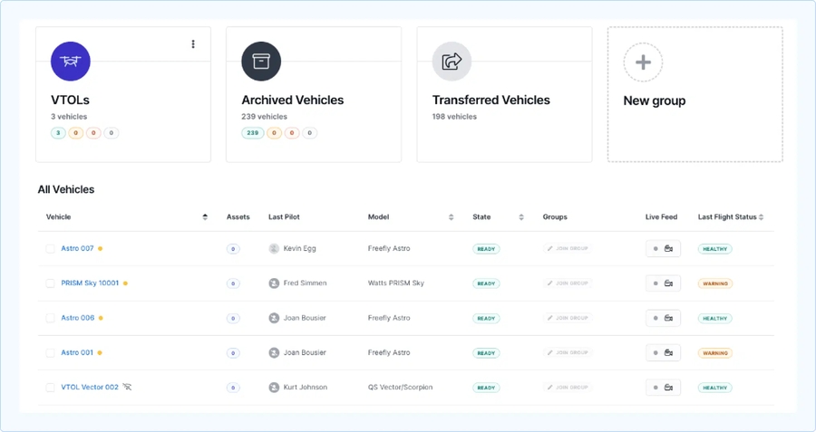
Mission Compliance: Ensure the mission conforms to all local laws, regulations, and airspace restrictions.
Mission Plan: Verify the mission was planned according to the guidelines outlined in the Plan section of this manual.
Terrain Altitude: Verify that altitudes are set appropriately against terrain height for the entire flight path.
Obstacle Clearance: Maintain a vertical separation of at least 25 meters above the highest obstacle at every stage in the fixed-wing portion of the flight.
Path Clearance: Verify the mission path is free of obstructions for at least 200 meters in each horizontal direction.
VTOL Operations: Confirm proper application of VTOL takeoff and landing procedures.
Takeoff: Ensure the takeoff location is free from obstructions up to the transition altitude for 500 meters in the transition direction and 200 meters in every horizontal direction. In case of a failed airspeed sensor, the vehicle will fully engage the pusher motor for 25 seconds and fly in a straight line before aborting the transition due to a failure to achieve the transition airspeed.
Landing Site: Verify the landing site is free of obstacles and structures taller than the transition altitude.
Orbit Land Pattern: Ensure the orbit and landing approach are clear and maintain at least 25 meters above any obstacle.
Wind Direction: Align the vehicle’s takeoff and landing paths against the wind, pointing the vehicle in the direction from which the wind is coming.
Land Approaches: Ensure obstacle-free sectors are selected for the landing approach. The vehicle will automatically perform the back transition to multirotor mode into the wind, or get as close as possible to this direction given the limitations of the selected sectors.
VTOL Operations: Plan takeoff altitude to be 15 meters above obstacles and landing altitude 25 meters above obstacles.
Holding Pattern: Set VTOL takeoff orbit with at least 25 meters of clearance above obstacles. The orbit's altitude is always 80 meters relative to the takeoff location.
Takeoff: Ensure the takeoff location is free from obstructions up to the transition altitude for 500 meters in the transition direction and 200 meters in every horizontal direction. In case of a failed airspeed sensor, the vehicle will fully engage the pusher motor for 25 seconds and fly in a straight line before aborting the transition due to a failure to achieve the transition airspeed. Strong winds can shift the orbit in any direction, altering its shape. For example, due to wind influence, a circular orbit may change in its shape to become more oval.
Wind Direction: Align the vehicle’s takeoff and transition against the wind, pointing the vehicle in the direction from which the wind is coming.
Maintenance Cycles: Ensure the vehicle is within preventive maintenance intervals.
Regulatory Compliance: Confirm the airframe complies with all local rules and regulations and is permitted to fly the intended mission.
Parts Inspection: Check for damage, dirt, secure mounting, and fastening:
Fuselage: Undamaged and clean.
Skid Antennas: Undamaged.
Propellers: Correctly mounted, securely fastened, and free of damage and dirt.
VTOL Arms: Properly mounted and fastened.
VTOL Motors: Spinning freely, no play in the bearings.
Pusher Motor Pod: Correctly mounted, securely fastened.
Pusher Motor: Spinning freely, no play in the bearings.
Wings: Mounted securely, undamaged, and clean.
Wing Tip LEDs: Clean and operational (if applicable).
Elevons: Moving freely, undamaged, and clean.
Payloads: Correctly mounted, and payload-dependent checks completed (SD cards/USB sticks installed if required).
Battery Check: Ensure the flight batteries are undamaged, with no dents or swelling, and that all cables and connectors are intact. When flying with two batteries, ensure both are fully charged and have the same charge level.
Pitot Tube: Clear of damage, dirt, and water. After flights in rain, store the DeltaQuad Evo in a dry space for 24 hours to dry the airspeed sensor and tubes.
Landing Gear: Free of damage and dirt. The vehicle should be launched from a solid surface free of mud as the landing gear can collect mud and add weight to the vehicle.
Hatch: Free of damage and dirt.
Ice, Snow, or Mud: Ensure the landing gear is free from ice, snow, or mud as this can result in the landing gear legs freezing onto the VTOL arms not being able to deploy during landing.
Solid Surface Launch: The vehicle should be launched from a solid surface free of snow or mud.
Pitot Tube Icing: Verify the pitot tube is ice-free.
Battery Temperature: Batteries must be heated above 10°C before takeoff.
Sunlight Exposure: Avoid exposure to direct sunlight when idle for more than 5 minutes to prevent overheating.
Flight Batteries: Ensure batteries are properly installed, power connectors securely connected, and fully seated. When operating with an auxiliary battery, ensure the locking latch is rotated 90 degrees to secure the battery.
Payloads: Verify payloads are installed and detected. Custom payloads must not exceed 3 kg in total.
APDS Payload: Ensure APDS cargo cannot move excessively during flight. (If applicable, use compartment dividers.)
System Status: The DeltaQuad Evo status OLED reads Ready to fly.
Hatch Security: Ensure the hatch is secured, with the closing mechanism pushed down, locked, and sitting flush with the fuselage.
Vehicle Positioning: Position the vehicle on the designated takeoff/landing zone, facing into the wind.
Weather Conditions: Ensure weather conditions are within mission tolerances. Verify that wind speed and gust limits are within safe VTOL and fixed-wing operation parameters.
Communications Check: Confirm communication between UAV and GCS is reliable. If in use, check the VPN connection.
GCS Warnings: Verify no warnings appear on the GCS.
When operating in areas prone to GPS jamming or spoofing, ensure the GPS signal quality and potential interference are checked using platforms like GPS Jam or Skai Data Services for your specific region. Avoid takeoff if the GPS signal is compromised.
In the event of losing GPS lock during flight, the vehicle will initiate a Return to Launch (RTL) using inertial navigation. Navigational drift may occur, especially in windy conditions, and the pilot may need to manually correct the course.
GPS Lock: Ensure stable GPS lock with at least 10 satellites.
Vehicle Status: Confirm “Ready to Fly” status (green label) in AMC. If Position not available, do an . (Oscillate the drone around its three axes by approximately ±30 degrees.)
Failsafe Settings: Confirm safety features are set correctly, and failsafe settings are properly configured in case of communication loss or low battery.
As stated in this , when an RTL (Return-to-Land) is triggered, the vehicle will return from its current location to the landing pattern in a straight line at its current altitude. If the current altitude is below the Minimum Return Altitude, the vehicle will ascend to the set Minimum Return Altitude during its return. The Minimum Return Altitude must be set higher than any obstacle in the mission area. The RTL failsafe will ignore all and the boundary of a complex .
Physical Orientation: The vehicle's current physical orientation should match the heading observed on GCS.
Battery Check: Verify in AMC that the flight battery indicator shows a full charge (greater than 95%).
Complete AMC Preflight checklist: Ensure all items are completed, including:
Ground Equipment Charge: Ensure ground equipment has sufficient charge to perform the mission.
Airspeed Sensor: Verify positive airspeed in telemetry. To test provide airflow in front of the pitot tube.
To access the interactive Preflight checklist in AMC, click on the Vehicle Status Indicator in the screen's upper left corner.
The Vehicle overview window opens. Click on the Preflight checklist tab in the lower-left corner of the window.
Go through each step of the Preflight checklist. The checklist can be reset to start over by clicking on the reset icon on the upper-right side of the screen.
You can enforce the Preflight checklist. Navigate to AMC menu -> Setting -> General -> Fly View.
Before each flight, the pre-flight checklist from the manual needs to be completed. The interactive Preflight checklist in AMC is part of that checklist, as the actuators will be checked, for example. It is NOT sufficient to only go through the interactive Preflight checklist in AMC.
Be sure to push the connector in fully to ensure a secure connection. If the connectors are not fully joined, the vehicle will still be able to switch on but the connectors could overheat. During the flight, due to vibration, the battery plugs could even come loose resulting in the vehicle losing power.
When powering up the DeltaQuad Evo, it will go through an initialization routine that can be monitored on the Evo's LCD display located above the avionics bay:
After the successful initialization, the LCD will read "Ready to fly".
If the initialization can't be completed due to an error, the LCD will give information indicating how to resolve it.
The following is a complete list of messages and their explanations.
Ready to fly
The vehicle has found no errors and is ready to fly.
Left wing not detected
The left wing is not detected. Please attach the left wing.
Right wing not detected
The right wing is not detected. Please attach the right wing.
Reverse payloads
The heaviest payload should be in the rear (slot 1). This message indicates that the payloads should be reversed. The payload in slot 1 should be installed in slot 2 and vice versa.
No payloads found
The software has not found any payloads. When flying without payloads the empty payload boxes (placeholders) need to be installed.
Every payload box carries information about its weight and weight distribution. This information is stored on the I/O board of the payload box.
Depending on the installed payloads the DeltaQuad Evo will automatically balance itself by moving the main battery tray to the front or to the back.
The DeltaQuad Evo can compensate to a greater extent for tail heaviness rather than nose heaviness. That is why the main battery tray can move more forward than backward. This is the reason why the heavier payload must be always installed in payload slot one, the most aft payload slot close to the pusher motor.


The DeltaQuad Evo Enterprise Edition comes with the DeltaQuad Controller. It provides the communication link between your UAV and the ground systems.
The following section gives a basic overview of the DeltaQuad Controller and its functionality.
The DeltaQuad Controller has three working frequency bands of 800MHz(806-826Mhz), 1.4GHz(1427-1467Mhz), and 2.4GHz(2401.5-2481.5MHZ). It comes with interchangeable antennas to match the frequency band of choice.
The 800MHz frequency band is not capable of transmitting a video link.
To connect your UAV to the DeltaQuad Controller simply switch on the UAV and press and hold the POWER button (5) on the controller for 5 seconds. Once the controller is booted up, the main menu will display.
Before launching your flight control system it is recommended to connect the controller to a mobile hotspot or Wi-Fi network. The controller uses internet connectivity to load satellite maps and for LTE connectivity to the UAV. The DeltaQuad controller must be connected to a 5Ghz mobile hotspot or WiFi network. As one of the primary communication links for the controller is based on 2.4 GHz, these networks will not be displayed. When using a mobile phone hotspot, please configure the hotspot for 5 GHz. Alternatively, you can insert a SIM Card for internet connectivity.
Except for switch 1, and push buttons 4 and 5, no other switches, dials, or push buttons have a dedicated function.
Before takeoff, always center all switches, and turn all dials to the left.
For the advanced operator, it is possible to assign functions to unassigned switches or dials. This will be discussed in a later chapter.
Under NO circumstances attempt to fly the DeltaQuad Evo in Manual Mode! We do not recommend assigning the Manual Mode to any of the switches or reassigning this mode to any of the programmed switches.
The DeltaQuad controller comes with a rich interface offering HDMI, 4G SIM card, USB, Type-C, LAN, Micro SD card, and PPM.
*The HDMI port only supports a resolution of 1900x1200. When using the HDMI port to connect to an external display, you need to make sure that the resolution of 1900x1200 is supported by the external display. It is not possible to change the HDMI output resolution in the controller.
The DeltaQuad Controller can operate continuously for approximately 5 hours. If more operation time is required, the controller can be charged during operation.
To charge the controller, open the rubber cover between the antennas and attach the provided USB charger to the USB-C port. The controller requires high-voltage charging. Standard USB chargers or USB sockets from laptops are not always capable of providing high voltage, but they will extend the battery life of the controller.
To shut down the controller, press and hold the power button until the shutdown menu appears. Select "Power off" to shut down the controller.
The DeltaQuad EVO will proceed to these waypoints, continuing in Aerodynamic mode.
To plan mission items such as regular waypoints select the Waypoint Tool from the Plan Tools on the left side of the screen.
Click anywhere on the map to designate a location for the waypoint.
After placing the waypoint on the map, the Mission tab in the Plan Item Selector on the right side of the screen will open.
Choose and set up the desired mission item from the Waypoint type tab.
When AMC is used in three options are available.
The Altitude mode is the altitude above the launch elevation.
Set the altitude for the waypoint with the altitude slider.
The default range can be changed in the Application Settings. Settings>General>Plan View>Waypoints Maximum Altitude
When changing the altitude of a waypoint, the next waypoint's altitude is automatically set to that value.
The Altitude mode is the altitude above the launch elevation.
Set the altitude for the waypoint with the altitude slider.
Set the duration of how long the DeltaQuad EVO should orbit at the designated location.
Set the radius of the Orbit. We recommend a minimum radius of 100m. 75m is possible in calm winds.
Choose the vehicle's exit point from the Orbit.
At the bottom of the Mission tab, you can edit the position of the mission item, or delete it.
If the vehicle's altitude differs from the altitude of the next mission item, the vehicle will fly in a straight line toward that mission item.
The vehicle will not ascend or descend immediately to the altitude of the next mission item before reaching it.
If the vehicle can't reach the altitude of the next mission item due to an insufficient climb or descent rate, the vehicle will orbit at the location of the mission item to finish climbing or descending to the item's altitude.
The Altitude mode is the altitude above the launch elevation.
Set the altitude for the waypoint with the altitude slider.
Set the radius of the Orbit. We recommend a minimum radius of 100m. 75m is possible in calm winds.
Choose the vehicle's exit point from the Orbit.
At the bottom of the Mission tab, you can edit the position of the mission item, or delete it.
When using Orbit (altitude), the operator must be especially cautious about terrain collisions.
Orbit (altitude) is practical for reaching a desired altitude before the flight path continues or when the vehicle's climb or descent rate will not be sufficient to reach the required altitude en route.
This section describes the use and functionality of geofences.
A geofence is a virtual boundary set around a specific geographic area. It restricts where the UAV can fly, often for safety, regulatory compliance, or privacy reasons. If a UAV approaches this boundary, it can trigger automated actions, like alerting the operator, pausing, or returning to a safe area. Geofencing helps prevent UAVs entering restricted zones, such as airports, military areas, or other sensitive locations.
Slot 1: No payload
No payload was found in slot 1 (rear payload). Both payloads should be occupied. With a dual payload, this message should not appear.
Slot 2: No payload
No payload was found at slot 2 (front payload). Both payloads should be occupied. With a dual payload, this message should not appear.
Slot 1 not Configured
The payload printed circuit board (PCB) for the payload in slot 1 has not been programmed.
Slot 2 not Configured
The payload printed circuit board (PCB) for the payload in slot 2 has not been programmed.
Balancing Error XXmm
The payload makes the vehicle to nose or tail heavy and cannot offset the center of gravity (CG) with the nose battery (between -5 and +35 is ok).
Automatic balancing
The system is balancing the vehicle by moving the nose battery fore or aft.
Arming denied: XX
Arming UAV is denied because of reason XX.
Battery not fully charged
Battery level below 80%.
Nose battery moved XX mm
The vehicle moved the nose battery XX mm to offset the imbalance caused by the payloads.
Payload to heavy
The total payload weight is above 3000 grams. This is not within vehicle specifications.
Updating params
The vehicle parameters are being updated to accommodate the payloads.
Writing parameters failed
There was an error while writing the parameters.


Control Surfaces Check: Perform control surfaces functionality check.
Mission Upload: If applicable confirm the mission plan is uploaded.
Clear Takeoff Area: Check for a clear takeoff area and airspace.
Return to Land
NOTE: RTL must be deactivated before the vehicle will accept any other commands.
5
Push button
POWER
Press and hold for 5 seconds: power on/off
Press: screen on/off
6
Left joystick
In hover mode
Stick up: climb
Stick down: descend
Stick left: yaw left
Stick right: yaw right
In fixed-wing mode
Stick up: gimbal up
Micro SD card slot
12
PPM
Number
Type
Function
1
3 position switch
FLIGHT MODE
UP: Altitude flight mode
CENTER: Altitude flight mode
DOWN: Mission flight mode
2
Right joystick
In hover mode
Stick up: move forward
Stick down: move backward
Stick left: move left
Stick right: move right
In fixed-wing mode
Stick up: descend (nose down)
Stick down: climb (nose up)
Stick left: bank left
Stick right: bank right
3
Joystick
Gimbal zoom
4
Number
Interface
6
HDMI*
7
4G SIM card slot
8
USB
9
Type-C
10
LAN (RJ45)


Push button
11
One or more geofences can be placed in the Plan View and uploaded to the vehicle. This is possible with or without a takeoff, waypoint, or landing item being present. This is beneficial when operating the vehicle with the Quick Takeoff functionality while requiring complex geofencing.
A faster and simpler way to create a geofence is to use the Geofence Failsafe Trigger option in the Safety tab, as explained in the following section.
Navigate to the Geofence option in the Safety tab: AMC Menu -> Vehicle Overview -> Safety -> Geofence Failsafe Trigger.
When AMC is running in Normal Mode, the Action on breach tab provides the following four options to choose from. Set the action required for the planned operation.
None
No action
Warning
A warning message will be displayed/announced.
Hold mode
The vehicle will enter Hold mode and orbit at the location and altitude where the failsafe action was triggered.
Return mode
The vehicle will enter Return mode and fly directly to the designated landing location at the set return altitude, then land.
When enabling Max Radius, a geofence will be placed with the DeltaQuad Evo at its center. Set the values for Max Radius and Max Altitude (HGT) in the respective fields.
Max Radius
The horizontal radius of the geofence cylinder around the Home Position. Alternatively, a circle can be drawn and freely positioned in the Plan View. The horizontal geofence is disabled if set to 0.
Max Altitude
Height of geofence cylinder. Altitude geofence disabled if 0.
The Max Altitude is referenced to the takeoff location (HGT), not above ground level (AGL). Special care must be taken when operating in an area with varying ground elevations. For more information, please read the chapter Geofence Failsafe Trigger.
Go to the Plan View and navigate to the Extra tab in the Mission Editor on the right side of the screen: AMC Menu → Plan View → Extra.
In the Extra tab, two geofence options are available: Polygon Fences and Circular Fences. Add a geofence by clicking the plus sign next to the desired geofence shape. A geofence will be positioned at the center of the map.
3. The Polygon Fence can be repositioned by dragging the geofence while holding the inner vertex (green point). Clicking on the outer (white) vertices gives the option to remove a vertex or enter the geocoordinates for that specific point. The outer vertices can also be dragged in any direction to shape the polygon into the desired form.
Clicking any of the plus signs on the geofence adds another vertex.
Hold and drag any of the vertices to shape the polygon.
Hold and drag the inner green vertex to reposition the fence in any direction.
The geofence can be set to be inclusive or exclusive. By default, the Type is set to Inclusion. Change the Type by selecting Exclusion in the respective tab.
Inclusionary geofence: A geofence where the vehicle stays within the defined area; an action is triggered before breaching and leaving the area.
Exclusionary geofence: A geofence that defines an area the vehicle shall not enter; an action is triggered before breaching and entering the area.
If a height limit for the geofence is required, this can be set in the Geofence Failsafe Trigger tab in the Safety settings. Enable Max Altitude (HGT) and set the desired value. The Action on breach will be triggered when the vehicle crosses the set altitude.
The Max Altitude is referenced to the takeoff location (HGT), not above ground level (AGL). Special care must be taken when operating in an area with varying ground elevations.
When the Extra tab (Geofences) is selected, two Plan Tools on the left side of the screen are available. The full functionality of these tools can be reviewed in the chapter Plan View. The File option allows you to save the geofence(s), and the Center option provides multiple ways to center the view.
When adding a Circular Fence, it will be placed at the center of the map.
The radius can be adjusted by holding and dragging the outer vertex left or right. Alternatively, a value for the radius can be set in the Radius tab in the Mission Editor on the right side of the screen.
The Circular Fence can be repositioned by holding and dragging the inner vertex in any direction.
As with the Polygon Fence, the Circular Fence Type can be set to either inclusive or exclusive.
If a height limit for the geofence is required, this can be set in the Geofence Failsafe Trigger tab in the Safety settings. Enable Max Altitude (HGT) and set the desired value. The Action on breach will be triggered when the vehicle crosses the set altitude.
The Max Altitude is referenced to the takeoff location (HGT), not above ground level (AGL). Special care must be taken when operating in an area with varying ground elevations.
When the Extra tab (Geofences) is selected, two Plan Tools on the left side of the screen are available. The full functionality of these tools can be reviewed in the chapter Plan View. The File option allows you to save the geofence(s), and the Center option provides multiple ways to center the view.
When an inclusive geofence is planned with the DeltaQuad Evo outside the geofence, the following two scenarios can occur:
The vehicle will not be able to arm while on the ground, as it is outside the geofence.
The vehicle will trigger the Action on breach when airborne, as it is outside the geofence.
When a exclusive geofence is planned with the DeltaQuad Evo inside the geofence, the following two scenarios can occur:
The vehicle will not be able to arm while on the ground, as it is inside the geofence.
The vehicle will trigger the Action on breach when airborne, as it is inside the geofence.
As stated in this manual, when an RTL command is triggered, the vehicle will return in a straight line to its designated landing point. If an exclusionary geofence or the boundary of a complex inclusionary geofence lies between the vehicle and the landing point, the vehicle will ignore the geofence and pass through it during its return.
In Altitude and Position Mode, the vehicle will breach both inclusionary and exclusionary geofences for a small distance until the RTL command is triggered. The system has a delay in responding to a geofence in these modes because the system needs to verify for a longer period that it has breached the geofence.
Rally Point and Breach Return Point are not supported by the DeltaQuad Evo.
(When AMC is running in Advanced mode, Rally Points are available in the Plan Tools on the left side of the screen, and the option to set a Breach Return Point is available in the Mission Editor on the right side of the screen. These options are not supported on the DeltaQuad Evo.)
The vehicle flies toward the location and altitude specified by the user. Once it arrives, it will proceed to the next mission item. If there are no further mission items following the Waypoint, the vehicle will orbit at the Waypoint's location.
The vehicle flies toward the location and altitude specified by the user. Once it arrives, the vehicle will initiate an orbit and continue to circle that position. When the specified Orbit Time elapses, it will proceed to the next mission item.
The vehicle flies toward the location at its current altitude. Once it arrives, the vehicle will initiate an orbit and start climbing or descending to the user-specified altitude. When the altitude is reached, the vehicle will continue to the next mission item.


This section describes how to control your vehicle using the DeltaQuad Controller.
Auterion Mission Control is installed on your DeltaQuad Controller. This is the main application to control your UAV and the installed payload(s). Before launching AMC please carefully review the DeltaQuad Controller section.
Before starting a flight a mission needs to be planned to instruct the vehicle on the takeoff and landing patterns.
This can be done by planning a full mission in the Plan View or by planning a takeoff and landing in the Fly View.
For example, when flying a survey mission with a mapping sensor, you can choose to plan a full mission in the Plan View. For a speedy deployment during a surveillance mission, it might be more practical to plan only the takeoff and landing in the Fly View. It is possible to take control of the vehicle after the takeoff and initiate a Return command when the mission has ended. The vehicle will use the landing pattern from the mission plan or from the planned landing to execute a return command.
When starting AMC the Fly View is displayed. You can choose to plan the takeoff and landing in the Fly View. For a full mission, you need to switch to the Plan View. You can switch to the Plan View by pressing the Plan View icon in the left-side command bar.
Please review the for detailed information on how to plan a mission.
Once your mission is uploaded you can return to the Fly View by pressing the Fly View icon in the left-side command bar. If you created a takeoff and landing in the Fly View it is not necessary to switch views. Once you have performed the you can start the mission by pressing and holding the Mission Start button. If the button is not displayed you can press the Action button in the left-side command bar. The Mission Start button will reappear. When pressing and holding to confirm the takeoff your vehicle will start its motors and takeoff.
Before starting your first flight, you will need to be familiar with the DeltaQuad Controller button and joystick functions as described in the .
NOTE: Before launching, make sure all switches are in their center position, all dials are turned all the way to the left, and the deploy button is switched off.
Once the vehicle is launched and has transitioned to fixed-wing flight mode, you can control the flight of your vehicle through the following methods.
While the vehicle is in flight, you can select the Orbit or Fig 8 command from the pilot controls on the left side of the screen. Tap anywhere on the satellite map to choose the Orbit's or Fig 8's location. On the right side of the screen, the altitude slider will appear. By dragging it up and down you can set a desired altitude for the orbit or Fig 8.
After confirming the command by pressing and holding the command button, the vehicle will change course to the set location and adapt to the set altitude. When orbiting the DeltaQuad will keep a radius of 100m.
The vehicle can be controlled using the right-side joystick (2).
To activate the joystick control, switch the flight mode switch (1) to ALTITUDE mode. In this mode, the vehicle will fly in a straight line at its current altitude until a joystick command is received.
Moving the joystick left or right will make the vehicle change direction.
Moving the joystick forward or backward controls the altitude of the vehicle. A forward (up) joystick movement moves the nose of the vehicle down and decreases altitude. A backward (down) joystick movement pulls the nose of the vehicle up and increases altitude.
If the vehicle loses connection to the DeltaQuad Controller while it is flying in Altitude mode, it will automatically return home, regardless of the Safety settings.
NOTE: For inexperienced pilots, the joystick controls can seem counterintuitive. It is recommended to practice joystick operation in close proximity while flying at sufficient altitude.
When giving an Orbit or Fig 8 command, the altitude can be changed. A vertical slider will appear on the right side of the screen that allows you to select a new altitude. Once the correct altitude is selected, and the location for the Orbit or Fig 8 command is chosen slide the slider to confirm the command.
When the vehicle is following a mission path, it will always track the altitude as defined in the mission plan. When resuming a mission the vehicle will immediately change the altitude to match the currently active waypoint.
When the vehicle is in ALTITUDE, HOLD, or TARGET FOLLOWING mode, the mission can be resumed by moving the flight mode switch to the MISSION position. Alternatively, the mission can be resumed by tapping on the ACTION button on the FLY screen and selecting "resume mission".
Please make sure to disengage the TARGET FOLLOWING mode before returning to MISSION flight mode.
At any point in the flight, the vehicle can be returned by activating the RETURN button (4). Alternatively, RETURN mode can be activated by tapping on the RETURN button on the FLY screen, and sliding to confirm the command.
In RETURN mode, the vehicle will immediately fly towards the landing pattern that was defined in the mission. The landing pattern consists of a circle-to-altitude item, a direction and altitude on which to exit the circle, and a landing coordinate.
When the RETURN mode is activated, the vehicle will fly at its current altitude towards the 'circle to altitude' part of the landing pattern. When reaching this location the vehicle will circle down to the indicated altitude, and complete the circle until it has reached the indicated exit heading of the circle. It will then proceed toward the landing coordinates, transition to multirotor flight mode, and land in the indicated position.
Nudging refers to making small manual adjustments to an automated flight path, typically during the landing descent. This feature allows operators to slightly alter the course or trajectory of the DeltaQuad Evo without fully taking over manual control. It's commonly used to ensure smoother landings, especially in cases where minor corrections are needed due to environmental factors like wind or obstacles
After the Evo transitions from fixed-wing mode to multirotor mode, the vehicle will deploy the landing gear and descend to the planned landing point.
The operator can halt the descent by pushing the left joystick forward.
The vehicle will maintain its altitude and position. The right joystick controls the vehicle's position. Moving the joystick forward, backward, left, or right changes the vehicle's position relative to its current heading.
The left joystick controls the vehicle's descent and heading. Moving the joystick up will halt the descent while returning returning the joystick to the middle position or moving it down will resume the descent. Moving the joystick left or right changes the vehicle's heading (yaw).
The maximum default hover time of the DeltaQuad Evo is 90 seconds. After 90 seconds the vehicle will force-land at its current location.
The multirotor mode should not be used for more than 90 seconds as the system can overheat when utilized longer.
The most common situation where it is practical to use stick control in multirotor mode is during the landing to reposition the Evo if necessary.
This can be achieved by using the NUDGE function.
After the Evo transitioned from fixed-wing mode to multirotor mode, the vehicle will deploy the landing gear and descend to the planned landing point.
The operator can halt the descent by moving the left joystick up. The Evo will hold its altitude and position. The RIGHT joystick (2) controls the position of the vehicle. Moving this joystick, forward, backward, left, or right changes the position of the vehicle relative to its current heading.
The LEFT joystick (6) controls the vehicle's altitude and heading. Moving the joystick UP will halt the descent. Moving the joystick to its middle position or down will continue the descent. Moving the joystick left or right changes the heading (yaw) of the vehicle.
Controlling the Evo in Altitude mode when flying as a multirotor should be avoided due to its temporary drivetrain limitations. Flying manually for longer than 90 seconds in multirotor mode is not recommended.
During takeoff or landing, your vehicle is in multirotor mode. Multirotor mode means the 4 motors for Vertical takeoff and Landing are activated.
To take control of the vehicle in multirotor mode, change the flight mode switch to ALTITUDE mode. In this mode, the vehicle will hold its position and altitude until joystick commands are received.
The LEFT main joystick (6) controls the vehicle's altitude and heading. Moving the joystick UP will increase the altitude. Moving the joystick down will decrease the altitude. Moving the joystick left or right changes the heading (yaw) of the vehicle.
The RIGHT joystick (2) controls the position of the vehicle. Moving this joystick, forward, backward, left, or right changes the position of the vehicle relative to its current heading.
For joystick (manual) control, the flight mode must be changed. Press the Mode button in AMC's Top Bar. Two options will be offered: Altitude and Position mode.
Altitude Mode: The DeltaQuad Evo will automatically maintain its altitude while the pilot controls the horizontal direction. It relies solely on the IMU for stabilization and navigation, without utilizing the compass or GPS. During Altitude mode, drift can occur due to wind influences.
Position Mode: The DeltaQuad Evo will hold both its altitude and position until adjusted by stick input. For stabilization and navigation, it uses the IMU along with the compass and GPS for enhanced accuracy.
Altitude mode provides faster movement in multirotor mode compared to Position mode.
After activating either Altitude or Position mode, the vehicle will hover in place until stick input is given. In Altitude mode, more drift can be expected.
When the DeltaQuad Evo and the Ground Control Station are powered and connected the video feed will be visible in AMC either in the main screen or in the small video screen in the bottom-left section of the FLY view. You can switch the main screen between the satellite map and video feed by tapping on the small screen in the bottom-left corner.
On the right side of the fly screen, the camera controls are displayed. These controls allow you to change the mode of the camera system.
Stick down: gimbal down
Stick left: gimbal left
Stick right: gimbal right


The camera controls window allows you to set the following camera modes:
Track
By pressing the "Track" button and subsequently choosing an object within the video display, you can instruct the gimbal to track that specific object. This functionality is most effective when there is a clear contrast between the object and its background.
Target tracking is the mode where the camera will remain focused on a target. The target can be moving or static. Activate target tracking by tapping on the Track button. Simply tap anywhere in the video feed and the camera will enter tracking mode and track the target that was tapped on. You can tap several times to fine-tune your target tracking mode.
When a target is being tracked, a white square is displayed on the object that is being tracked. By moving the camera joystick, tracking is disabled and the camera returns to the previous mode.
POI
You can establish a Point of Interest (POI) on the map view by simply tapping the POI button and then tapping on your desired location on the map. Alternatively, you can set a POI while in camera view by selecting the POI option and tapping on the specific point of interest within the video frame. The gimbal will then make an effort to maintain focus on the selected POI's location on the ground.
GRR
In this mode, the camera will hold its position relative to the ground. This is the recommended mode for camera control. The joystick controls the camera.
OBS
In this mode, the camera will hold its position relative to the vehicle's movement. The joystick controls the camera.
LPOS
LPOS (Local Position) is the mode in which the camera tracks the orientation of the aircraft, so when it makes a turn, the camera maintains the same angle relative to the aircraft.
EO
(Electro-optical) Activates the RGB (normal color video) mode of the camera.
IR
(Infra-red) Activates the Infrared camera for night vision and seeing between foliage.
When clicking on the camera symbol the recording mode can be switched between photo and video recording.
The red button indicates the video recording mode.
The black button indicates the photo recording mode.
The -/+ button controls the zoom of the camera. The zoom level is indicated by degrees.
The fader button opens the camera menu with access to camera settings and general settings.
The camera settings tab gives access to the following options:
Camera: Switch between EO and IR mode. This mode can be also accessed via the camera controls in the Fly view.
EO Sharpness: This option gives three different degrees to boost the sharpness of the image.
White Balance: Switch between Automatic and Manual mode.
When White Balance is set to Manual a slider appears to set the white balance manually:
When IR is chosen as the camera mode more options will be available for this mode:
IR Polarity: In this tab, the operator can choose to have either Black Hot or White Hot.
IR Coloring: In this tab, the operator can choose between the Gray scale or the Color scale.
Non-Uniformity Correction: (NUC) After engaging the IR mode, the IR camera needs to be calibrated for a clear view. This is done automatically by the system. NUC performs this calibration which takes about 3 seconds.
Gimbal Mode: In this tab, the operator can switch between GRR, OBS, and LPOS gimbal modes. These camera control options are also available in the Fly view via the camera controls.
Video Bitrate: With this slider the video bitrate can be set. By default, the value is set to 2000. The higher the bitrate the better the video image will be but at the cost of the maximum telemetry distance.
Onboard Media Storage: With this option, you can enable or disable the Onboard Media Storage.
At the bottom of the window, the available storage for video recording will be displayed.
Roll Derotation: The camera is capable of keeping the video stream aligned with the horizon when the vehicle is banking. This is called Roll Derotation.
When roll derotation is active the video image displayed on the controller will rotate in such a way that the image remains level. The trade-off is that the video can show black corners when the vehicle is banking.
The settings tab on the upper right corner of the menu gives access to general settings:
Zoom Controls
Enables zoom controls in the camera control window.
Quick Gimbal Modes
Makes the gimbal modes (GRR, OBS, and LPOS) available in the camera control window.
Gimbal Angle Indicator
The camera angle (in degrees) will be displayed in the Fly view.
Gimbal Virtual Joystick
Enables a virtual joystick left of the camera control interface in the Fly view.
Invert Gimbal Controls
Iverts the gimbal controls.
Gimbal speed
With the slider, the gimbal speed can be set. It is set to Normal by default.
The grid option is either a square or a screen division by 3x3:
Target following is the mode where the vehicle actively follows a tracked target. To engage target following mode you will first need to track a target. Once a target is locked you can engage target following by giving the Target Following command. The command is located on the left side of the Fly view where the pilot commands are located.
The system will start following a target when these conditions are met:
A target is actively being tracked
The target is less than 2,000 meters away from the vehicle
Target following has been enabled
TIP: The camera can rotate 360 degrees. To avoid reaching the maximum rotation angle it is recommended to fly towards, follow, or directly above a tracked object.
When first entering target following mode the vehicle will switch its flight mode to "HOLD" mode. The target following system will then issue reposition commands every 1.5 seconds for as long as the target following conditions are met. If the conditions are no longer met the vehicle will remain circling the position of the last known target location. If the tracked target is lost you can re-engage target tracking by simply tapping on the object in the video feed, the system will follow any target selected target following is enabled and the conditions are met.
If the vehicle is flying above the tracked target, or if the vehicle is flying faster than the tracked target, it will circle above the target keeping the target in view at all times.
If target following is disengaged the vehicle will start circling its current position.

Switch position
Mode
Functionality
↑ Up
Altitude mode
The DeltaQuad will automatically hold its altitude and direction until changed by the stick input. For flight stabilization and navigation, it will only rely on the IMU and not make use of the compass and GPS.
- Neutral
Altitude mode
The DeltaQuad will automatically hold its altitude and direction until changed by the stick input. For flight stabilization and navigation, it will only rely on the IMU and not make use of the compass and GPS.
↓ Down
Mission mode
When engaging the Mission mode the DeltaQuad will continue it's mission from the active waypoint.


Camera Projection
When the map is selected in the Fly view the camera's Field of View is indicated by a blue cone.
Screen Grid
This option will display a grid overlay on top of the video image.


Before executing a mission the following conditions must have been met:
The mission must be planned in accordance with the guidelines set out in Planning a mission.
The Pre-flight checks must have been performed and passed.
The vehicle should be pointing with its nose towards the wind.
All flights must be started with a fully charged battery.
The operator and any observers must keep a safe distance from the vehicle, a 10m minimum is recommended.
When all checks are performed, and everything is set up and working properly, you can start the mission. The mission can be started by sliding the "Start mission" activator.
When the vehicle needs to be returned while executing a mission, the recommended method is to direct the UAV toward a waypoint that will provide a clean entry into the pre-defined landing sequence. You can change the active waypoint that the vehicle is following by clicking the desired waypoint from the fly screen and confirming the change request.
Please note: when changing the active waypoint, the vehicle will immediately change its altitude to the altitude of the selected item. It will not gradually climb or descend but reach the new altitude as fast as possible. It is therefore recommended to select a waypoint that has an altitude at which the vehicle can safely return from its current position. If a waypoint with a safe altitude is not available, it is recommended to first reposition the UAV to a safe location by tapping a location on the map. While repositioning the UAV it will maintain its current altitude.
Using the simulator is recommended to practice returning the UAV during a mission using the method described in this section.
The QuadChute is a safety feature that triggers an automatic transition from fixed-wing mode to multirotor mode in emergencies.
This typically happens if the vehicle detects a critical issue, such as loss of control, significant deviations from the flight path, or insufficient airspeed to continue safe fixed-wing flight.
When the QuadChute is activated, the DeltaQuad Evo stops flying as a fixed-wing aircraft and switches to multirotor mode, enabling it to hover and safely descend and land at its location.
This feature ensures the vehicle avoids dangerous situations, like crashing or uncontrolled descent, by leveraging its
After a QuadChute event occurs, the following guidelines must be followed:
Switch the Flight Mode to Position using the mode selector in the AMC’s Top Bar.
Throughout the mission, both the telemetry data and the vehicle should be monitored. This task can be performed by a single operator, but it is recommended to perform this task with one operator and an observer. The observer should continue to watch the vehicle and its surroundings and alert the operator of any problems or nearby traffic.
Note: It is highly recommended to practice the following exercise in the simulator several times before operating the vehicle.
From the flight screen, and when the vehicle is armed, the following key functions are available:
LAND: Land immediately.
The vehicle will land at its current location. If the vehicle is in Fixed Wing mode the vehicle will transition back to quadcopter mode first.
This button is called "Take off" while on the ground.
RTL: Return To Launch.
The vehicle will return to its takeoff point via the "Landing Pattern" command which consists of the "Loiter" waypoint and the "Land" item.
The vehicle will reach the "Landing Pattern" command in a straight line from its current location at its current altitude. If the current altitude is lower than the Return Home altitude in the Safety settings it will climb to this altitude. If the vehicle is flying in Quadcopter mode it will return to the "Landing Pattern" command and land in this mode. If the vehicle is in Fixed Wing mode it will return as Fixed Wing to the "Landing Pattern" command, perform a back transition when reaching the takeoff location, and land in quadcopter mode.
The advantage of facilitating the "Landing Pattern" command is that it will provide a clean entry into the pre-defined landing sequence and execute the transition and landing into the wind.
Note: using RTL is a last resort. The recommended method of returning the vehicle in fixed-wing mode is described in the section "Returning the vehicle during a mission" above.
PAUSE: The vehicle will hold its current position.
In Fixed Wing mode it will circle the current position with a radius of 100 meters. While in pause mode, when there are no open dialogs, tapping anywhere on the map will give you the ability to select "Goto location".
When sliding to confirm the goto command, the vehicle will proceed to the selected location.
ACTION: The "Action" button.
With the "Action" button the mission can proceed, or the flight altitude can be changed. The "Action" button becomes available when the vehicle is in HOLD mode (pause). See the picture below.
When tapping the action button two options become available.
CONTINUE MISSION will resume the mission towards the next waypoint indicated by a green color. If the option CONTINUE MISSION is not available you can resume the mission by switching to MISSION mode using the "Flight Mode" button.
The minimum and maximum altitudes can be set in the "Application Settings" under the "Q" icon.
Emergency Actions: This button will indicate the current state of the DeltaQuad.
When the vehicle is in flight (armed) this button can be clicked and the option to "Disarm" the vehicle will appear.
When clicking the "Disarm" button the emergency stop box will appear.
When confirming the emergency stop all motors will stop IMMEDIATELY. This procedure should only be used while the vehicle is on the ground or as a last resort to avoid damage to people or property.
Note: Using this function during flight will crash your vehicle and void your warranty.
Land: The vehicle will land at its current location. If the vehicle is in Fixed Wing mode the vehicle will transition back to quadcopter mode first.
FLIGHT MODE: This button displays the current flight mode. By tapping this button a new flight mode can be selected. Supported flight modes are HOLD, RETURN, and MISSION. Switching flight modes using this method will not require slider confirmation. Note: When a new flight mode is selected this will be activated immediately.
VTOL MODE: This button indicates if the vehicle is currently in multi-rotor or fixed-wing mode. Tapping this button will provide the option to switch modes.
At altitudes higher than 100m above ground, or in strong winds, it is not recommended to switch from fixed-wing to multi-rotor mode.
WAYPOINT items:
The waypoint items on the screen can be tapped. When tapped a dialog appears asking if the vehicle should proceed to the selected waypoint. When confirmed the vehicle will proceed in a straight line towards the selected waypoint. It will also immediately change to the altitude of the selected waypoint.
The operator should monitor the following:
The following should be monitored directly after takeoff while the vehicle is ascending vertically to its transition altitude.
Operator Action: LAND
During takeoff, the landing gear should retract at approximately 3 meters above the ground. If the landing gear fails to retract—either partially or fully—the operator must immediately initiate the LAND command. This will deploy the retracted landing gear, and the vehicle will autonomously land at the takeoff location.
If necessary, the operator can use the nudging function to reposition the vehicle. Use nudging with caution when the vehicle is close to the ground.
After landing, contact [email protected] for further assistance.
Toilet bowling Operator action: LAND The vehicle should take off in a straight line after the first few meters. If the vehicle starts "toilet bowling" (circling up) the mission should be aborted and a sensor calibration must be performed.
Not holding position Operator action: LAND The vehicle should take off in a straight line. If the vehicle starts drifting from its position more than a few meters it should be commanded to LAND. Contact support to have your log files analyzed.
Takeoff failure Operator action: DISARM If the vehicle fails to take off or only one-half of the vehicle rises it is likely that the quadcopter propellers are damaged, mounted incorrectly, or upside down. The operator should disarm the vehicle and review the propeller's configuration as described in the assembly section.
Excessive current draw Operator action: LAND If the current draw indicated by CURRENT from the telemetry display exceeds 180 Amperes the flight should be aborted. The vehicle could be overweight, flying outside of tolerable wind conditions, or has a malfunction. In the case of a malfunction inspect the vehicle for visible damage to the propellers or a higher resistance in any of the motors. If there was no evident damage then contact Vertical Technologies support for analysis.
After reaching transition altitude the vehicle will commence the transition to fixed-wing flight. (switching from quadcopter to fixed wing). It will transition into the direction that the vehicle was placed in, but wind can have an effect on the direction, especially if the vehicle is not positioned with its nose directly into the wind. The vehicle will engage full thrust for 15 seconds using its pusher motor. After this period it should navigate towards the takeoff location or the first waypoint.
No forward motion Operator action: LAND If the vehicle is not moving forward or is drifting with the wind and does not seem to transition towards fixed-wing there is likely a problem with the pusher motor or propeller.
Flying backward Operator action: LAND If the vehicle starts flying backward with increasing speed it is likely to have the pusher propeller mounted in the wrong direction. The transition should be aborted and the pusher motor should be inspected.
High current slow forward flight Operator action: RTL If the vehicle is moving horizontally in the direction of the first waypoint at low speed, with the quadcopter motors still engaged after 15 seconds, and the current draw remains above 30 Amperes, it is likely that the mission did not issue a VTOL TAKEOFF command but a TAKEOFF command. The vehicle will attempt to complete the mission in quadcopter mode. If this was not intended, RTL should be initiated by the operator. Note: The DeltaQuad can activate its pusher motor in quadcopter mode too. The spinning of the pusher motor is no indication that the vehicle is attempting fixed-wing flight.
Switch to multi-rotor mode Operator action: Transition to fixed-wing or LAND There are some conditions where the vehicle can switch to multi-rotor mode. These include loss of positional awareness or accidental mode switching by the operator. In these events, it is usually prudent to attempt to resume fixed-wing flight by pressing the VTOL mode switch (G). If this fails for any reason, the vehicle must be landed. When the vehicle is higher than 200m this must happen immediately as the multirotor mode may consume too much energy to complete a full return.
Abort error displayed due to loss of altitude or maximum bank angle Operator action: LAND This error is displayed on the Ground Control Station when the vehicle has activated the failsafe system. The UAV must be landed as soon as possible. Do not attempt to complete the automatic return sequence if the vehicle is higher than 100m or further than 800m from the home position. If the battery is lower than 35% it should always be landed. Use the map to locate a safe area to land the UAV and direct the UAV to this location. Then press the LAND button to land immediately.
After such an event the cause must be determined before a new flight is attempted. Please contact Vertical Technologies support for assistance in analyzing the cause of the failsafe event.
Excessive altitude loss Operator action: Return or LAND During and shortly after transition, the vehicle may lose some altitude, this is generally not more than 5 meters. In extreme cases (high payload, strong wind). This can be up to 8 meters. The vehicle should recover from this loss quickly, and regain and maintain altitude. Some altitude gain or loss may occur when banking (changing direction). This should not exceed 5 meters.
If the vehicle does not maintain altitude, or if the altitude error exceeds 10m and the vehicle does not recover from this altitude error an RTL should be commanded. If the vehicle does not adequately perform the RTL procedure (continues to lose altitude or fails to navigate back) a LAND instruction should be given. After a LAND instruction is given, and the vehicle is performing a landing in quadcopter mode, the RTL instruction can be given again to have the vehicle return in quadcopter mode. This should only be attempted when the vehicle is less than 1km from the takeoff site and more than 50% of the battery capacity is available.
The reason this can occur could be related to weight, balance, or a problem with the servos or pusher drive. A thorough inspection of the vehicle is required. If the problem can not be found and resolved you should contact Vertical Technologies support.
Failure to track the mission path Operator action: Return or LAND During the transition, the vehicle does not fly in the direction expected:
When the transition phase completes, the vehicle should fly towards its takeoff location or first waypoint. If the vehicle does not follow its intended path after the transition phase, an RTL should be commanded. If the vehicle does not adequately perform the RTL procedure (continues to lose altitude or fails to navigate back) a LAND instruction should be given. After a LAND instruction was given, and the vehicle is commencing a landing in quadcopter mode, the RTL instruction can be given again to have the vehicle return in quadcopter mode. This should only be attempted when the vehicle is less than 1km from the takeoff site and more than 70% of the battery capacity is available.
The reason this can occur can be related to a failure of the servo actuation or if a mission is incorrectly loaded.
Excessive pitch Operator action: Increase cruise throttle / Return The DeltaQuad should cruise at an average pitch angle between 3 and 9 degrees unless a change in altitude is commanded. If the pitch angle consistently exceeds 12 degrees while the vehicle is not attempting to climb to a higher altitude the cruise throttle should be increased. Increasing the cruise throttle can be done by changing the parameters as described in the Key parameters section. This parameter can be changed during flight. If this does not resolve the problem the flight should be aborted by issuing an RTL command. Note: When changing the cruise throttle during flight special care must be taken to monitor the battery level.
The reason for this could be related to sensor calibration, overweight, too low cruise throttle, or a problem with the fixed-wing drive. To resolve this attempt to level the vehicle as described in the sensor calibration section, verify the weight or increase the cruise throttle. If the problem persists please contact Vertical Technologies support.
Battery level and current consumption Operator action: Return The battery level percentage indicated in the top bar of the flight screen should be monitored throughout the flight. the percentage should always be higher than the relative distance the vehicle still has to travel. For example, if only 50% battery remains, more than 50% of the mission should have been completed. The CURRENT and CONSUMED values will also help determine this. The DeltaQuad should draw between 9 and 15 Amperes of current on average during cruise flight. This value increases;
The vehicle is flying significantly above sea level
If the vehicle is flying with maximum payload.
As the battery percentage drops.
Ground speed Operator action: Increase cruise throttle The DeltaQuad will generally maintain a constant speed through the air, but wind conditions will impact the effective ground speed. If the ground speed drops below 6 m/s the cruise throttle should be increased. Increasing the cruise throttle can be done by changing the parameters as described in the Key parameters section. This parameter can be changed during flight. Note: When changing the cruise throttle during flight special care must be taken to monitor the battery level.
When this happens the vehicle is likely flying in wind conditions that exceed the specified tolerance.
When the DeltaQuad is flying towards its last waypoint (the VTOL_LAND waypoint) it will determine the appropriate distance from the waypoint to initiate its back transition. The distance depends on the current ground speed and can vary between 5 and 100 meters from the land position. During the back transition, the DeltaQuad will activate its pusher motor in reverse direction to slow down.
Excessive overshoot Operator action: None If the vehicle overshoots its landing waypoint significantly and does not seem to slow down during back transition, there could be a problem with the pusher reverse system. The vehicle should be thoroughly inspected for loose connectors on the flight controller (specifically connectors 7 and 8 as indicated on the wiring diagram). If no problem was found with the connectors the vehicle should be grounded and undergo extended maintenance.
Unstable descent Operator action: None If the vehicle becomes unstable during landing the land speed as indicated in the safety features is likely set too high.
No auto disarm after touch down Operator action: Disarm The DeltaQuad should disarm automatically 5 to 10 seconds after touch down. If the vehicle does not disarm automatically the disarm command (emergency stop) should be sent. This command can be sent by pressing the "Armed" label.
The reason for this could be related to landing on a significantly uneven surface or slope. It can also indicate the sensors need calibration.
In the Plan View, you can create, edit and save missions, which can be uploaded to the DeltaQuad EVO. To plan a mission the DeltaQuad EVO does not need to be connected to Auterion Mission Control.
When opening Auterion Mission Control by default the Fly View will be selected. To change to the Plan View Click on the Menu icon in the upper left corner of the screen. A drop-down menu will open. Select the Plan tab.
The image below shows a simple mission that starts with a Start and a Transition Direction item. The mission continues to fly through three waypoints which are followed by a Mission End Action.
The steps for creating missions are:
The QuadChute will only engage at altitudes of 300 meters and below. If a critical issue is detected above this altitude, the vehicle will first attempt to descend to 300 meters in fixed-wing mode before engaging the QuadChute.
This feature serves as an essential fail-safe mechanism for maintaining safety, particularly during complex flights or in challenging conditions.
When operating in areas prone to GPS jamming or spoofing, and the vehicle lacks a GPS lock, Altitude mode must be used as it does not rely on GPS.
Altitude mode can be also enabled on the controller with Switch 1 in the up position.
If the vehicle's altitude is below or at the height of obstacles, ascend to a safe altitude by pushing the left joystick forward on the handheld controller.
When a safe altitude is reached, change the vehicle's heading so that its nose faces into the wind by using the left joystick to turn it left or right.
The wind direction can be viewed in the Fly View on the Telemetry Dashboard, indicated by the arrow in the top left corner of the compass.
When the correct heading is reached, use the Transition Command from the Flight Tools menu on the left side of the screen. The Transition Command will be available in the Flight Tools on the left side of the screen (Fly View) when running AMC in Advanced Mode (click five times on the AMC icon in the upper left corner of the screen).
After the vehicle has transitioned from multirotor mode to fixed-wing mode, return and land it by either using the planned Landing Pattern, if applicable, or the approach sectors in the Fly View. After the landing thoroughly check the vehicle for damage and fly-worthiness. When in doubt contact [email protected].
If the transition from multirotor mode to fixed-wing mode fails, land the vehicle immediately in a suited location by issuing the Land Command. During landing, the vehicle can be repositioned using the Nudging function on the handheld controller. The Land Command is also available under the Emergency Action in AMC's Top Bar.
If more vertical control is needed, the vehicle can be landed manually in Position or Altitude mode. Please note that the maximum default hover time is 90 seconds. After the timeout, the vehicle will force-land at its current location.
When the cruise throttle is set higher.
When the LiPo gets older.
When a power-consuming payload is active.
Change to Plan View.
Add commands to the mission and edit as needed.
Upload the mission to the vehicle.
Change to Fly View and fly your mission.
The following section describes all elements of the Plan View.
The Top menu bar consists of the same elements as the Fly View.
AMC Menu
Vehicle Status and Selector
Flight Mode
Emergency Actions and Arm Status
GPS Status
Radio Signal Strength
LTE Status and Signal Strength
Battery Status of the Vehicle
Battery Status of the Ground Control Station
Notifications Tab
On the left side of the screen, the Plan Tools are located. The Plan Tools provide tools for working with plans, including adding waypoints, inserting survey patterns, saving, loading, uploading, and downloading plans. Some of the options are only displayed when working on a particular type of plan.
The File Tool provides options to create a new mission plan, load and save plans on the Ground Control Station, and upload, download, or clear the plan on the vehicle.
Only valid options are enabled (e.g. Download is grayed out if there is no mission on the vehicle).
Storage
Open...
Open a plan file from storage, or clear the current mission in the Ground Control Station. The plan on the vehicle is not affected.
Save
Save previously opened or saved plans under the same name. AMC prompts to Save as if the file is new.
Save as...
Save the current plan under a new name.
Save Mission Waypoints as KML ...
Save the current mission as a KML file. KML files are used by Google Earth.
Recent Missions
Open a menu of recently created or loaded mission plans.
Upload
Upload the mission plan to the vehicle. Existing plans on the vehicle are cleared.
Download
Download the current plan from the vehicle. The current plan on the ground station is cleared.
Clear
Clear the mission plan on the vehicle and AMC. Disabled if no vehicle is connected.
Select the Waypoint Tool to enable adding new waypoints to the map.
Select the Point Of Interest (POI) Tool to enable adding a point of interest on the map. The camera gimbal will point toward the last POI created.
Select the Cancel POI Tool to cancel the last point of interest on the map.
Select the Pattern Tool to add or load a survey or corridor pattern. Additionally, a KML/SHP file can be loaded.
The Center Tool gives multiple options to center the map on a mission, home, vehicle, all items, or a specified location.
Mission
Center or zoom the map to include all mission waypoints.
All items
Center or zoom the map to include all plan items (missions, geofences, rally points)
Launch
Center the map at the point where the vehicle arms and takes off.
Vehicle
Center the map on the vehicle location. Disabled if no vehicle is connected.
Current Location
Center the map on the location of the Ground Control Station (AMC). Disabled if Ground Control Station does not have location or GPS.
Under the top menu bar, the mission statistics are located.
The mission statistics give information about the total mission distance, the maximum telemetry distance, and the total mission time.
The Upload Button uploads the current mission, geofence, and rally points to the vehicle. The button has two states.
Upload Required
The mission plan has been changed since the last upload. A new upload is required.
Upload
The mission plan has not been changed and the vehicle has the latest version stored. It may be re-uploaded anyway.
At the top right of the screen, the Plan Item Selector is located.
The Plan Item Selector sets the part of the mission plan which is being edited.
The Plan Item Editors are displayed below the Plan Item Selector. Different item editors are displayed for each part of the mission plan:
Start: In this tab, you can edit the values of the Mission Start Action which consists of the Start or takeoff item and the Transition Direction item.
Missions: The mission tab shows a list of editors, one for each item in the mission (waypoint, commands, etc.)
End: In this tab, you can edit the values of the Mission End Action. The Mission End Action can be either a landing pattern that consists of the Orbit and the Land item or only an Orbit item.
Extras: In this tab, you can add or remove GeoFence definitions, and select the current GeoFence region for editing on the map.
In the lower-left corner, the Measurement Tool is located. When clicking on it a menu will show.
The distance between two points can be measured or the area in the form of a selectable polygon. Clear all will delete all Measurement Tools on the map.
Coordinates can be entered manually.
At the bottom of the screen, the Terrain Altitude Indicator is located.
The Terrain Altitude Indicator is used to verify that the mission is set above ground level! It can be toggled visible or hidden using the button next to the Measurement Tool.
A red line indicates a ground collision!
In the upper left corner of the Terrain Altitude Indicator, you can select between three different altitude measurements.
Simply tap the letters next to the three dots to change to the different altitude measurements:
HGT
Height above takeoff
MSL
Altitude above Mean Sea Level
AGL
Altitude above Ground Level
Above the Measurement Tool and the Toggle button, the Scale Marker is located.
It indicates the scale of the map depending on how much the map is zoomed in or zoomed out.
To use the zoom function the mouse wheel can be used or two fingers when operating on a touchscreen.


Specified Location
Center the map on a specified location.
Enter geographic, UTM, or MGRS position information, to make it the new map center.


In the Fly View, missions are executed and monitored. The operator has two layouts available. By default, the map is the primary view and the video feed is the secondary view. You can change the layout by clicking the small window in the lower left corner.
Primary view - map, secondary view - video feed:
Primary view - video feed, secondary view - map view:
The smaller secondary window in the lower left corner can be resized by clicking the two arrows in the upper right corner. Simply drag the window to the desired size.
The following is a complete list of actions that can be taken within the secondary window.
Minimize or maximize the window
Adjust the size of the window
Detach the window from the lower left corner
Depending on whether the map or the video feed is the primary view, the available tools, and functions change. When the map is the primary view, all Fly Tools are available. When the video feed is the primary view the payload controls are available.
Map is the primary view: Video is the primary view:
All Fly Tools are available Payload controls are available
The available payload controls depend on the mounted payload. The payload controls will be discussed separately in the dedicated section for each available payload.
The following list describes all elements of the Fly View.
AMC Menu
Vehicle Status and Selector
Flight Mode
When installing Auterion Mission Control on a separate device such as a laptop or desktop pc, by default the Connection Manager will be available in the top bar of Auterion Mission Control.
The DeltaQuad EVO does not make use of the Connection Manager. In Settings>General>Miscellanous this option can be disabled.
The Telemetry Panel is located in the lower right corner of the screen. It is available in both layouts when the map is the primary view and when the video is the primary view.
Time since armed (approximate flight time)
Distance between vehicle and ground station
Compass (incl. vehicle heading, camera field of view, direction towards the Ground Control Station)
Vertical speed
Calibrated airspeed
Ground speed/horizontal speed
The following Fly View Tools are available on the left side of the screen when the map is primary.
Clicking the Flight Tools button in the lower-left corner of the screen will open an extra set of commands for controlling the vehicle. When the button is blue it is active and the extra set of commands will be visible. When the button is grey it is inactive and the extra commands will be hidden.
When using the Set Altitude command the Altitude Slider will be presented with a fixed Minimum and Maximum Altitude. The operator can choose an altitude between these values.
These values can be changed in Settings>General>Fly View.
Clicking the Map Tools button in the lower-left corner of the screen will open the Map Tools. When the button is blue it is active and the extra set of commands will be visible. When the button is grey it is inactive and the extra commands will be hidden.
The Marker Tool can be used to increase situational awareness. The set markers will be also displayed in the video feed.
When clicking on the Marker Tool button a menu will open.
Different Marker Tool Categories can be chosen by color and form. Click on the map to set the marker.
To delete a marker, select it on the map and click on Del. Selected in the Marker Tool menu.
The Measurement Tool button opens a menu.
The distance between two points can be measured or the area in the form of a selectable polygon. Clear all will delete all Measurement Tools on the map.
Coordinates can be entered manually.
The third item in the upper-left corner of the screen is the Flight Mode icon.
This item displays the vehicle`s current flight mode. When clicked the operator can change to the Position flight mode for manual control.
During operation, the Flight Mode icon can display the following modes.
GPS Status
Radio Signal Strength
LTE Status and Signal Strength
Battery Status of the Vehicle
Battery Status of the Ground Control Station
Notifications Tab
Telemetry and Compass
Video feed
Map Tools
Flight Tools
Fly View Tools
Estimated flight Time Remaining
Additional information depending on mounted payload
Map, Mission Items, Smart Actions, Vehicle Location (blue arrow), and Vehicle Track (red trail)
Wind direction and wind speed
Pitch Index
Altitude display - tap the letters above the three dots to change to the different altitude measurements:
Hold
Pauses the mission or any action. The vehicle will loiter at its current location.
Approach
Approach sector and Safe Areas can be modified.
Change Airspeed
Enables the operator to change airspeed. When clicked the Airspeed slider appears on the right side of the screen. Values between 14m/s to 25m/s are available.
Set Altitude
The altitude of the vehicle can be changed.
Map Layers
Changes between map layers
Load KML overly
Import KML file to the map
Measure
Opens the Measurement Tools
Manual flight mode is enabled. The vehicle can be controlled with the right joystick. When there is no stick input the vehicle maintains altitude and course.
HGT
Height above takeoff
MSL
Altitude above Mean Sea Level
AGL
Altitude above Ground Level
Takeoff
Command for takeoff - altitude, transition direction, loiter for takeoff, and approach sectors can be set.
Return
Return to the start location - the vehicle will return with the approach feature if at least one green sector is set. If no green sector is available the planned landing pattern will be ues.
Mission
Starts or resumes the planned mission.
POI
Depending on the payload a Point of Interest can be set. The camera will follow the specified location while the vehicle will remain on its flight path. The Point of Interest can be removed by clicking on Disable PIO .
Orbit
Sets an Orbit with selectable altitude, radius, and loiter direction.
Figure of 8
Sets a figure of 8 with selectable figure size, and altitude. The figure of 8 automatically realigns when a POI is set to keep the POI in the field of view.
Center Map
Centers the map on the vehicle
Marker
Set markers for situational awareness
Clear Path
Delete last flightpath to clear the map
VTOL Takeoff
Flight mode during takeoff
Mission
Flight mode in which the vehicle executes a planned mission.
Hold
Flight mode when the Hold, Orbit, or Figure of 8 command is given.
Return
Flight mode when executing the Return command.
Land
Flight mode when Landing in the Emergency Actions has been chosen.


Position


